Steady State Analysis – Indian Grid
The approval of grid connectivity requires the completion of a steady-state analysis. Before proceeding, every solar, wind, or BESS project must pass this phase. Most project delays begin here. A single subpar study results in rejection, review sessions, and iterative redo. This study examines the behavior of the plant under typical grid conditions. No shortcomings were considered. Switching occurrences were not considered. Only real operating circumstances were examined.
 The main goal is straightforward: the plant should not interfere with the grid. This study addresses one important question. When your plant is connected to the grid, is it safe? The steady-state restrictions are explicitly defined by the CEA regulations and the Indian Grid Code. At the PCC, the voltage must remain within the allowed range of 1.1pu to 0.95pu. Support for reactive power should be 33% of Plant Real Power capacity. The loading of equipment must not exceed the rated limits given by OEM’s. Before approval, utilities rigorously check these standards. Voltage regulation remains a significant challenge for CTU/STUs. At the PCC, the voltage must always be within certain bounds. Internal buses also need to conform.
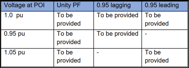
Both operational extremes must be clearly demonstrated. Plants must sustain the grid voltage according to the Grid Code. The injection and absorption of reactive power must be demonstrated. The results are directly affected by the choice of control mode. The power factor and voltage control modes must be justified. Reactive power modeling errors result in an outright rejection.
The foundation of steady-state analysis is load-flow analysis. It determines the amount of power that moves through the transformers, cables and Transmission lines. The voltage of each bus was checked. This draws attention to the weaknesses of the network. Approval was not granted for non-converged cases. Prior to submission, each result must be verified. Several operational scenarios are necessary. maximum output under minimal demand. highest load with a low generation. The normal state of operation is as follows: different grid behaviors are reflected in each situation. The reviewer becomes doubtful when scenarios are skipped. It is believed that there is a single line or transformer outage. The system must remain within its bounds. There was no voltage infraction or overheating. This demonstrates the grid dependability with a single-component failure.
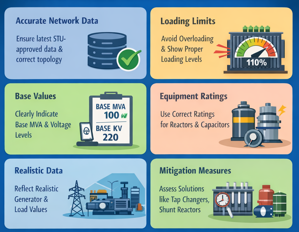
Transformers and transmission lines have certain restrictions. The steady-state analysis verified these boundaries in all situations. Overloading shortens the grid life and harms the equipment. Overloads are not tolerated by utilities, even for brief periods. The loading percentage must be displayed properly. The base of this study is accurate network data. The most recent STU-approved network data are required. The outcomes of incorrect topologies are incorrect. The bus voltage levels must be in line with the grid. Realistic conditions must be reflected in the generator and load data. Every outcome is affected by the base MVA and voltage choices. Confusion during the review was caused by incorrect base values. Base selection is routinely questioned by the utilities. The report must include a clear indication of the base values. The right impedance values must be the tap locations that correspond to the actual operational circumstances. The correct ratings must be used for the reactors and capacitors. It is imperative to adhere to the inverter capability curves. Rejection is a common outcome of the assumed values. Industry-standard tools such as PSS®E, Dig SILENT Power Factory and PSCAD steady-state models are the only tools that utilities accept. The choice of tools must align with the study objectives. If the results are to be verified, they must be repeatable. Numbers are provided by the software, but engineers must provide context. It is necessary to explain the voltage infractions. It is necessary to justify or reduce the overloading. Reviewers want comprehension, not screenshots. If there are infractions, mitigation measures must be suggested. Shunt reactors, capacitor banks, tap changer modifications, and control mode adjustments must be assessed. was used while modeling the transformers.


No comment