Voltage Ride Through Capability Requirements for Renewable Power Plants
Background
With the increasing penetration of renewable energy sources such as solar PV and wind, maintaining grid stability during voltage disturbances has become a critical requirement. Modern grid codes mandate that Renewable Power Plants (RPPs) — also known as Power Park Modules (PPMs) — must remain connected and support the grid during both low and high voltage events. This capability is commonly referred to as Voltage Ride Through (VRT) and includes both Low Voltage Ride Through (LVRT) and High Voltage Ride Through (HVRT) performance requirements.
Purpose and Application
These scenarios collectively cover the expected voltage excursion envelope defined in most international grid codes. They are typically simulated in PSCAD, PowerFactory, or similar EMT environments to demonstrate grid-code compliance, validate model performance for connection studies, and fine-tune converter control and protection settings.
Understanding the Voltage Withstand Capability Diagram
The voltage withstand (VRT) profile defines how long a generating unit should remain connected at various voltage levels following a network disturbance. It typically includes both low-voltage and high-voltage ride-through regions.
 — X-axis: Time
— Y-axis: Voltage in per-unit (p.u.) at the POC
— Blue Curve: Conventional synchronous generating unit (SGU)
— Red Curve: Renewable Power Plant (PPM)
The PPM curve reflects the converter-based plant’s capability limits and response expectations during and after a fault.
Typical LVRT and HVRT Test Cases for Renewable Power Plants
The following cases represent typical voltage disturbance scenarios evaluated during model validation and compliance testing of renewable power plants (RPPs). Each case corresponds to a specific level of retained voltage at the Point of Connection (POC), derived from the applied fault impedance relative to the network source impedance.
1. LVRT with Zero Remaining Voltage (Zf = 0 Ω)
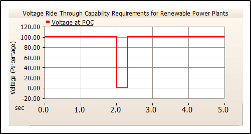
This scenario represents the most critical low-voltage ride-through (LVRT) condition, corresponding to a three-phase bolted fault at the Point of Connection (POC). During this event, the terminal voltage collapses to 0 p.u., and the generating plant is required to remain connected throughout the specified fault duration (typically 0.3 s). This test case evaluates the converter’s capability to withstand a solid (zero-impedance) fault condition and sustain operation while injecting reactive current in accordance with grid code requirements.
2. LVRT with 50 % Remaining Voltage (Zf = Zs)
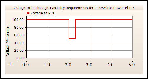
In this scenario, the fault impedance equals the system source impedance, resulting in a retained voltage of approximately 0.5 p.u. at the POC during the fault. This case represents a moderate remote fault and evaluates the Inverter’s dynamic performance under partial voltage support conditions.
3. LVRT with 70 % Remaining Voltage (Zf = 2 × Zs)
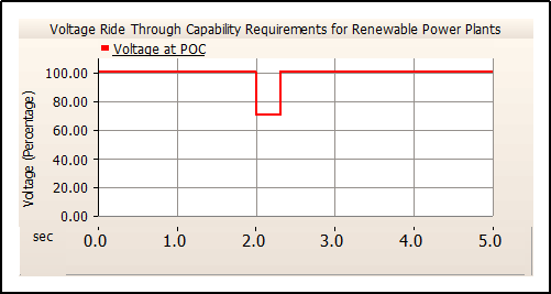
In this case, the fault impedance is twice the system source impedance, resulting in a shallower voltage dip of approximately 0.7 p.u. at the POC. This test verifies that the renewable plant can sustain stable operation and maintain reactive current control under mild fault conditions without causing unnecessary protection operations.
4. LVRT with Zero Remaining Voltage, Followed by 1-Second Ramp to 0.8 p.u.
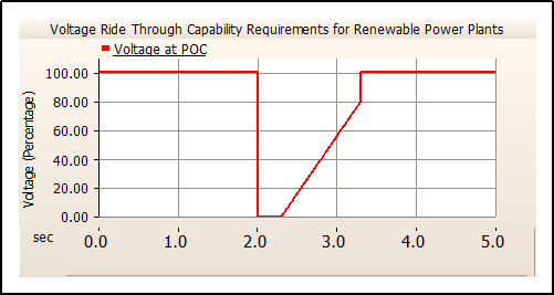
LVRT with zero remaining voltage, followed by a 1-second ramp to 0.8 p.u.: This composite case simulates a severe fault followed by gradual system voltage recovery after fault clearance. The voltage remains at 0 p.u. for the first 0.3 s and then ramps linearly to 0.8 p.u. over 1 s. It is employed to assess the plant’s dynamic voltage support capability and the smooth transition from faulted to post-fault operation.
5. Unbalanced LVRT scenarios
Unbalanced LVRT tests evaluate the converter’s ability to withstand asymmetric voltage dips caused by phase-specific faults. These scenarios include various fault types—single-line-to-ground (LG), line-to-line (LL), and double-line-to-ground (LLG)—with different remaining voltage levels at the POC. The tests aim to: Verify the converter’s ride-through performance under unbalanced fault conditions. Assess negative-sequence current injection and compliance with
grid-code requirements. Ensure a smooth transition from faulted to post-fault operation without unnecessary protection trips.
6. HVRT – Temporary Overvoltage (TOV) with 1.2 p.u. for 1 s (Yf = jXc)
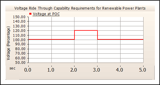
This case represents a temporary overvoltage, typically arising from network switching or capacitor energization. The POC voltage rises to 1.2 p.u. for 1 s, modeled via a shunt capacitive element (Yf=jXc). It is used to verify the converter’s overvoltage tolerance, DC-link protection, and control recovery under high-voltage stress conditions.
7. HVRT – Temporary Overvoltage (TOV) with 1.15 p.u. for 3 s (Yf = jXc)
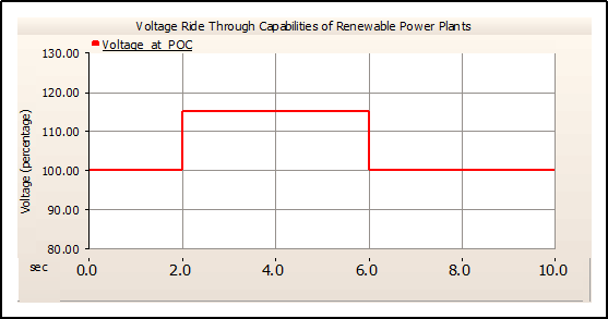
This case represents a temporary overvoltage, typically arising from network switching or capacitor energization. The POC voltage rises to 1.15 p.u. for 3 s, modeled via a shunt capacitive element (Yf=jXc). It is used to verify the converter’s overvoltage tolerance, DC-link protection, and control recovery under high-voltage stress conditions.
8. HVRT – Temporary Overvoltage (TOV) with 1.3 p.u. for 0.2 s (Yf = jXc)
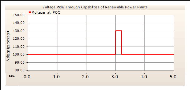
This case represents a temporary overvoltage, typically arising from network switching or capacitor energization. The POC voltage rises to 1.3 p.u. for 0.2 s, modeled via a shunt capacitive element (Yf=jXc). It is used to verify the converter’s overvoltage tolerance, DC-link protection, and control recovery under high-voltage stress conditions.
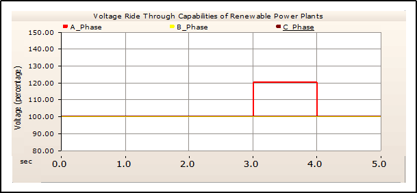
9. Unbalanced HVRT scenario – Single Phase TOV
Unbalanced single-phase HVRT tests assess the converter’s capability to remain connected and operate stably during asymmetric high-voltage conditions. These scenarios typically involve a single-phase overvoltage at the Point of Connection (POC) while the other phases remain within normal voltage limits. The objectives of these tests are to: Verify the converter’s ride-through capability and control stability under unbalanced high-voltage conditions. Evaluate positive- and negative-sequence voltage behavior and the corresponding current response in accordance with grid-code requirements. Ensure the converter transitions smoothly from the overvoltage condition back to normal operation without triggering protection malfunctions or disconnections.


No comment