1.Introduction
Generally, Protection coordination is a bottom-up approach. For any network, if protection device coordination is need to be performed, should start from the end equipment/bottom-most feeder.
In the example SLD, the LV side of the Trafo2 must be coordinated first, and particularly MCC has to be enabled with the LV release settings. Then the MV side of the Trafo 2 needs to be coordinated with the LV side. After these MV relay coordination need to be performed.
LV circuit breakers are equipped with two types of trip units.
- Thermal Magnetic trip units
- Solid state or Electronic trip units
Thermal magnetic trip units come with a fixed value of settings. It can not be modified according to the changing conditions at the site. Whereas the Electronic trip units have adjustable settings, It could be adjusted at any time according to the changes in the site. So it suggested using Electronic trip units for the LV Circuit Breakers.
2. Electronic Trip units

The electronic trip unit uses a microprocessor to process the current signal and operate the circuit breaker opening in case of fault.
The letters LSIG signify the type of protection and available adjustments on certain trip units.
- L = Long Time (Overload protection)
- S = Short Time (Short circuit protection of low-level faults)
- I = Instantaneous (Short circuit protection of high-level faults )
- G = Ground Fault (Equipment ground fault protection)
2.1 Long Time (LT) setting
LT gives over-current protection. It reacts to overload conditions and determines how much current the circuit breaker will carry continuously throughout its lifetime. It senses the overload and protects the equipment according to the setting.
For the LT setting two inputs are required.

- LT pickup – At the current above which the release picks up.
- LT band – At the time when release trips after the LT pickup.
2.1.1 LT pickup


LV releases have tolerance factor in LT pickup setting.
For Example from the Figure 1, 3200 was given as a LT pickup. LT pickup have some error band. It varies with respect to the manufacturers. For example TCC curve in the figure shows the LT setting of the ABB’s MCCB with the release of PR112.
Though the LT pickup is set at 3200A, the release operates in the range of 2880A
to 3520A. This means this release have the tolerance of -10% to +10%. Its clear that this release pickup at 2880A itself though the setting is for 3200A.
Even though it picks up at 2880A it is not necessarily have to trip at the same value. it may endure for infinite time. But if the release encounters >3520A, it trips according to the LT band value.

Min Tolerance Value |
Max. Tolerance Value |
It defines the minimum pickup current value – the minimum current at which the release pickup |
It defines the maximum holding current value – the maximum current up to which the release holds. |
There is a possibility that release pickup at 2880A |
There is also another possibility that release may not pickup upto 3520A |
If the minimum tolerance is negative value, it reduces the effective rating of the Circuit breaker itself. That means CB rated for 3200A but it may pickup at 2880A with -10% min. tolerance |
Maximum tolerance always in the positive side. This known as maximum holding current. |
NOTE: In order to utilize the breaker up to its full rating. The min. pickup tolerance is fixed at +ve side by manufacturers.

Figure 1: TCC Graph of L Setting
2.1.2 LT – Band
It should be selected to provide clear discrimination with downstream protection.
Say example for motors,
It should be above the starting characteristics and below the damage curves. (Hot and cold start curves).Because protection should not mal-operate during the starting and it should isolate the motor before the damage.
Function of LT band varies with the manufacturer’s design. In the example TCC cure, SACE PR112 is shown. For SACE PR112, LT band is defined as the at the set time, release will encounter the three times of the LT pickup value.
For example, if LT band is set at 6. As (3×3200) 9600A trips at 6 seconds. Like LT pick of the release this LT band too have an error band.

This particular release have error band of +20% for max. clearing time and -20% for min mum clearing that.
It is clear from the Figure 1 that LT setting pickup the 9600A at anytime between 4.8s to 7.2s.
LT band should be adjusted to protect equipment in such a way that above starting characteristics and below damage curves. And it should maintain clear discrimination between downstream protection device’s setting.
2.2 Short Time (ST) setting:
ST provides the protection against short circuit faults with defined delay and it acts as the backup protection for the downstream protection devices.

For the ST setting three inputs are required for the release.
- ST pickup- The minimum current at which the realease pickup
- ST band- The minimum time delay at which the release trips after the pickup
- Ix t- the intentional Time delay
2.2.1 ST pickup


ST pickup also have an error band as LT pickup.
2.2.2 ST band/Short Time delay (tsd):

It should be coordinated to maintain the clear space with the downstream. Value of the ST band depends on the setting of protection device and downstream and upstream. It should be set above the Maximum tolerance of downstream setting and below the minimum tolerance of the upstream setting.
Assume downstream set value for ST band is 50ms and it has 20% maximum tolerance so it has the maximum operating time of 60ms and so ST band setting value should be adjusted to operate at >60ms including the minimum tolerance. Similarly have to ensure that this maximum tolerance is not overlapping with the upstream setting.
2.2.3 Ixt

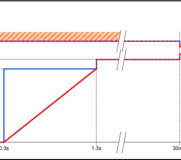
For Example in the case1, the release trips the CB at 0.04s for the fault current of 5760A, when Ixt is set at OUT. In the case2, the release trips the CB at 1.23s for the same fault current when Ixt is set at IN.
Generally it is suggested that to set Ixt as OUT, to trip the CB without any intentional time delay, unless the curve overlaps with the downstream protection
ST could be setted with or without intentional time delay. If Ixt is set at IN, the release takes more time to trip the CB and If Ixt is set at OUT the release takes lesser time than the IN case. IN refers to the inverse characteristics of curve and OUT refers to the definite time curve.

Figure 3: Case 2
2.3 Instantaneous Setting (I)
Insataneous have to be turned on only for the end equipments as Motors. And also the feeders which don’t have any downstream protection. Strictly it is applicable only for bus which can not have further down stream. and strictly not applicable for the upstream protection. When ST is enabled it is recommended that not to enable the I protection.


Unlike LT and ST settings, “I” don’t have a time delay. It trips the CB instantaneously, as quick as possible, as the name refers. But it has the error band in the pickup setting as similar to LT and ST pickup.
Asymmetrical factor is considered for the “I” protection of motor feeders only. Because when CB closes for the motor starting, all the three phases may not draw a current in pure sinusoidal wave, so the asymmetrical factor is considered for the motor feeders.
When asymmetrical factor is considered, we could neglect the Safety margin and max. over voltage factors.
2.4 Ground Setting (G)
“G” provides the protection against the unbalance currents, leakage current and earth fault. G setting is similar to the ST settings.

2.4.1 Ground Pickup
Since the LV system is mostly unbalanced, it is suggested to set the Ground pickup as the 20% of the rating. And most of the LV releases have the minimum set value 20% only, so we cannot set below the 20%.
![]()

2.4.2 Ground Band
Minimum available setiing is recommended for the motor/Capacitor feeders (i.e) end equipment feeders. And for the upstream feeder’s setting minimum discrimination should be ensured as similar to the ST settings.
2.4.3 Ixt – Needs to be selected as per the ST settings.
Important Points:
LT |
Max & Min pickup tolerance |
Max. & Min clearance time |
ST |
Max & Min pickup tolerance |
Max. & Min clearance time |
I |
Max & Min pickup tolerance |
–NA– |
G |
Max & Min pickup tolerance |
Max. & Min clearance time |
Each setting have its own tolerance. For example L may have ±5% tolerance for pickup value but ST may have ±20% tolerance. And it is applicable for the tolerances of the clearance time as well.
As per IEEE242, to ensure correct selective operation and to avoid mal operation there should be proper coordination between curves of different protective devices.

CSb – clear space between curves with upstream minimum-melting curve adjusted for pre-load.
CSc – some manufacturers may also recommend a safety factor.
3. LV RELEASE COORDINATION
Generally, Protection coordination is a bottom-up approach. For any network, if protection device coordination is need to be performed, should start from the end equipment/bottom-most feeder.
In the example SLD, the LV side of the Trafo2 must be coordinated first, and particularly MCC has to be enabled with the LV release settings. Then the MV side of the Trafo 2 needs to be coordinated with the LV side. After these MV relay coordination need to be performed.
As lumped loads are imaginary concepts, it is not suggested to perform simulation of LV release coordination. Start the coordination from SDB & MCC protection.
One-Line Diagram – OLV1 (Edit Mode)

3.1 Calculations for LSG settings of SDB Feeder

TCC GRAPH FOR PHASE PROTECTION

TCC GRAPH FOR PHASE PROTECTION

3.2 Calculations for LIG settings of MCC-Motor

3.3 Calculations for LSG settings of MCC feeder (CB7 & CB8)

3.4 Calculations for LSG settings of PCC I/C (CB5):

LT band and ST bands were set in way to maintain a clear discrimination between all the protection and damage curves.


Awesome sir .
Please make a video and post on you tube so that we can follow simulation as well.
this is a treasure form me and every engineer need to learn the real engineering
Thermal Magnetic trip device also having adjustable setting. But it was specified above that TM trip device is always fixed one.
Mostly thermal have adjustable setting and Magnetic will be fixed or adjustable.