
Short Circuit Current Calculations for Symmetrical and Unsymmetrical faults
It is not practical to design a power system which is free from failure. Hence we need to design the system which is capable of withstanding the faults till the fault is cleared by circuit breakers. It is necessary to select the circuit breaker which has the capability to interrupt the worst case fault current. In order to do that we need calculate the worst case fault current. This article talks about the calculations of Short circuit current for various faults (three phase fault, single line to ground fault, Line to Line fault and double line to ground fault) for the given network.
Case 1: Under No load
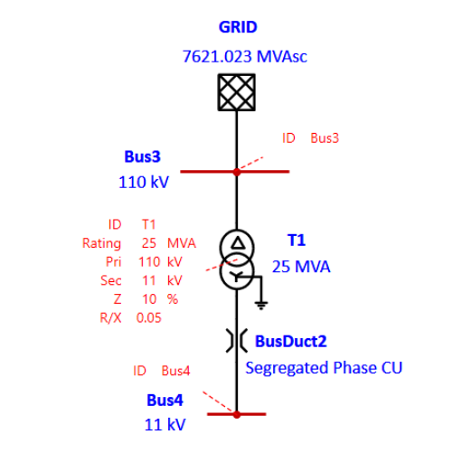
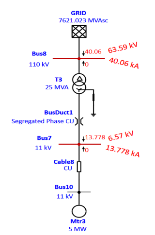
Grid: 110 kV, Short circuit current of 40 kA, X/R = 14,
Transformer: 25 MVA, 110/11 kV with %Z of 10, X/R = 20
The fault is created at 11kV bus and the fault impedance considered to be zero (Bolted fault).
The step by step procedure and calculations are made below.
Procedure & Calculations:
Step 1: Let us consider 100 MVA and 110 kV as base MVA and Voltage respectively
Step 2: Find the R P.U & X P.U values and validate with ETAP results
Step 3: Convert the Impedance to common base i.e, 100 MVAb
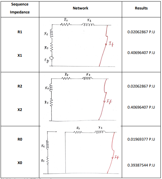
Step 4: Draw the Impedance diagram and find Positive, Negative and Zero Sequence
impedance.
Step 5: Calculate the fault current and validate with ETAP results
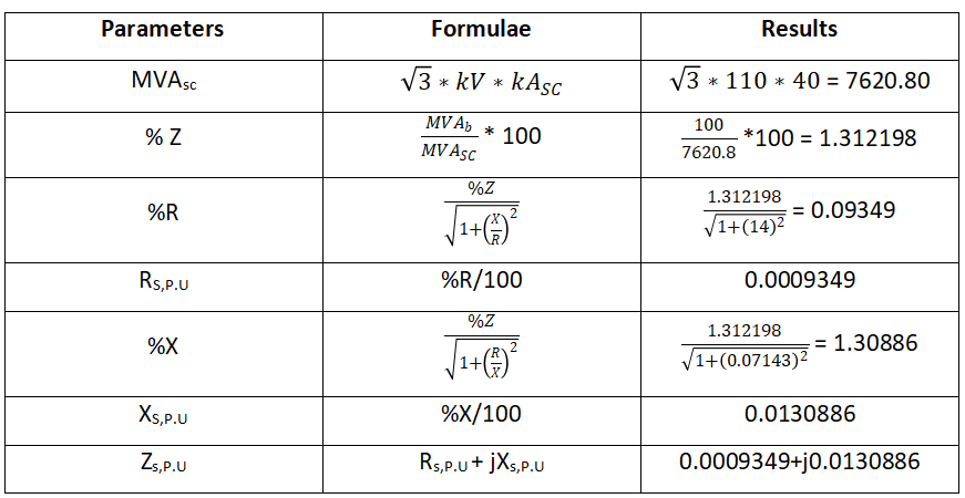
Grid:
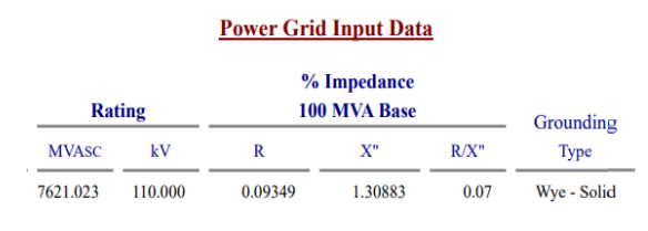
Validating with ETAP Result
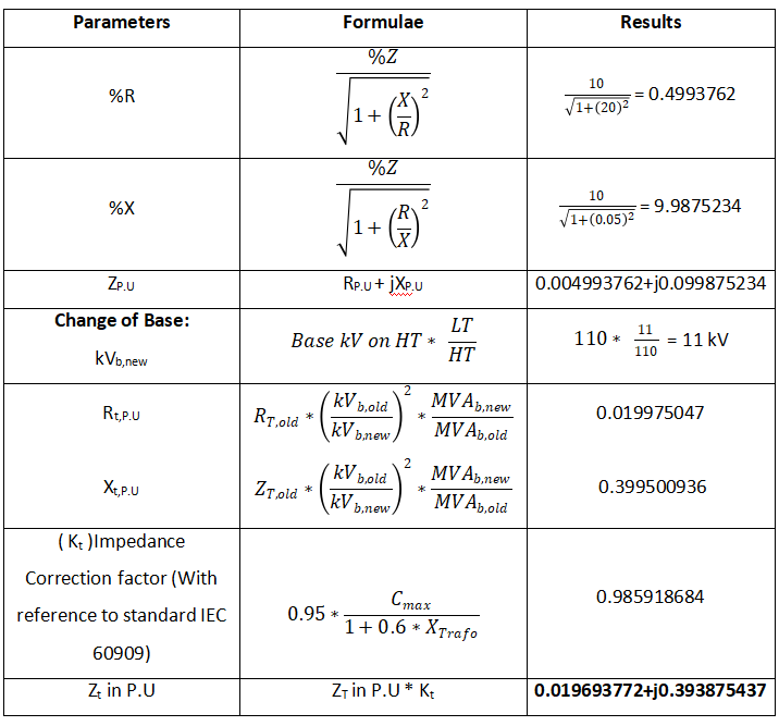
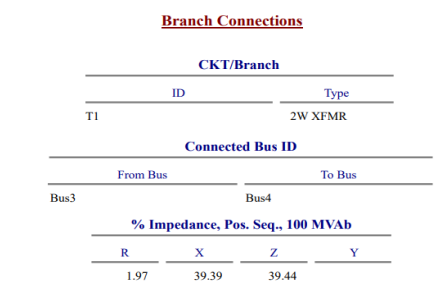
Transformer:
Validating with ETAP Result:
Positive, Negative and Zero sequence diagram for the given network
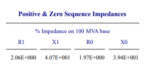
Validating with ETAP results:
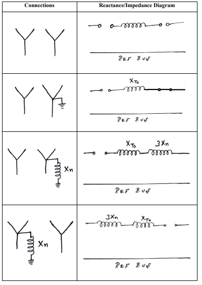
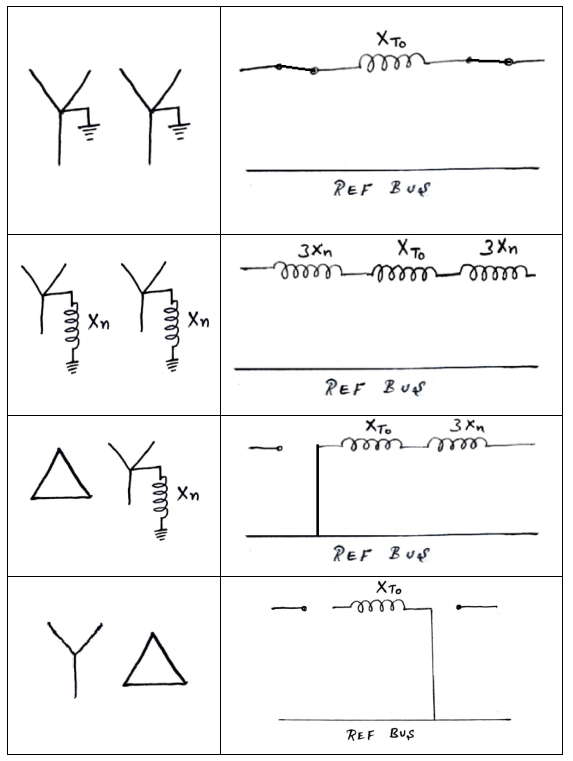
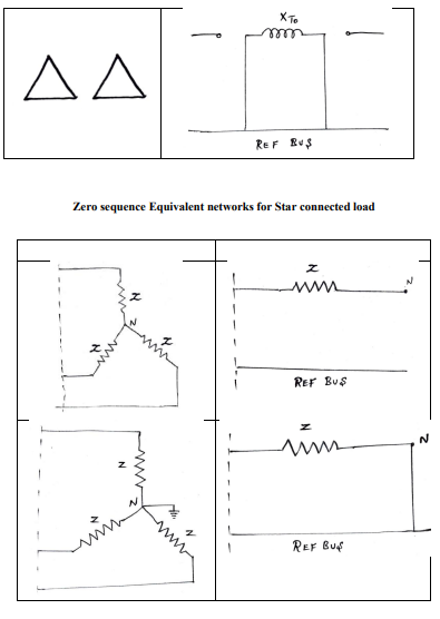
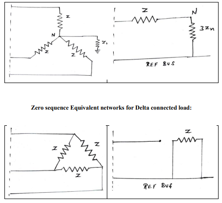
Zero Sequence Equivalent network for three phase transformer with Different Connections
Three Phase Fault:
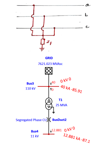
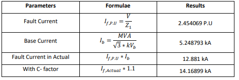
Single Line to Ground Fault:


Line to Line Fault:
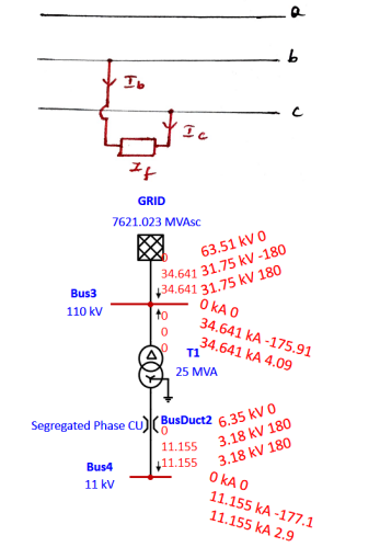
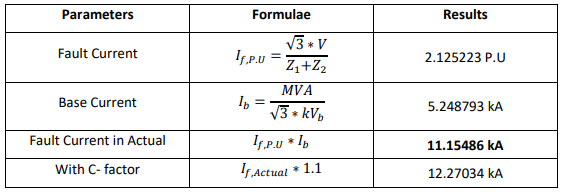
Double Line to Ground Fault:

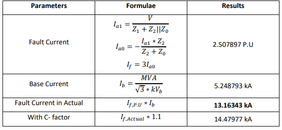
Case 2: With Motor load
Motor Ratings: 5 MW, 3-ph Ind Motor with 90% Eff, 95% P.F, X/R = 10.825, 𝑋′′= 15.319
Cable Ratings: 1-3/C 240 Sq.mm CU cable, R = 0.098 ohm, X = 0.09 ohm
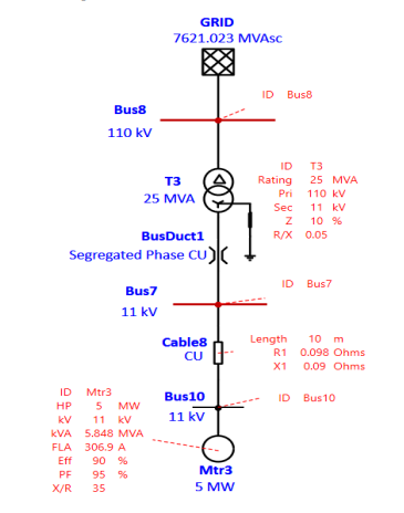
Motor:
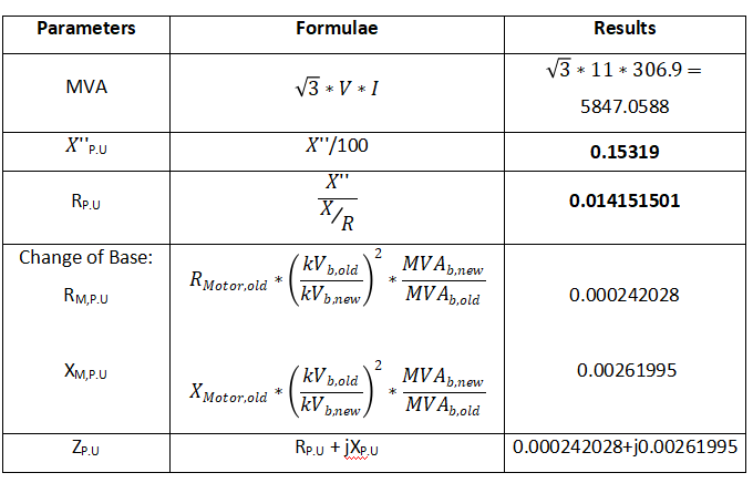
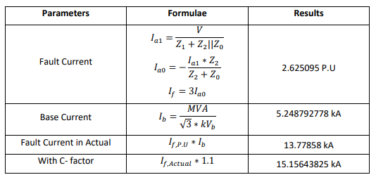
Validating with ETAP Results:
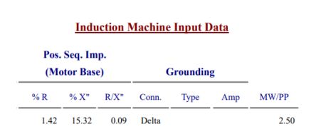
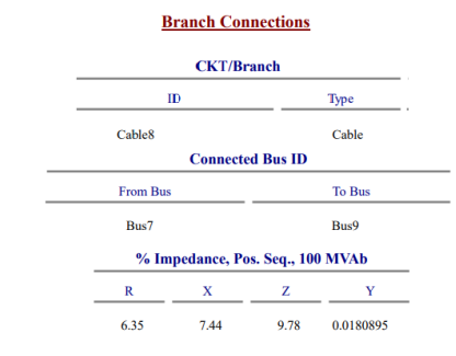
Cable:
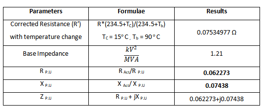
Validating with ETAP Results:
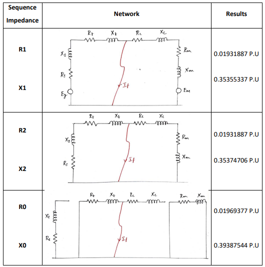
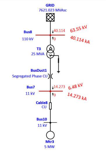
Positive, Negative and Zero Sequence Network:
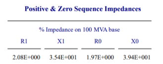
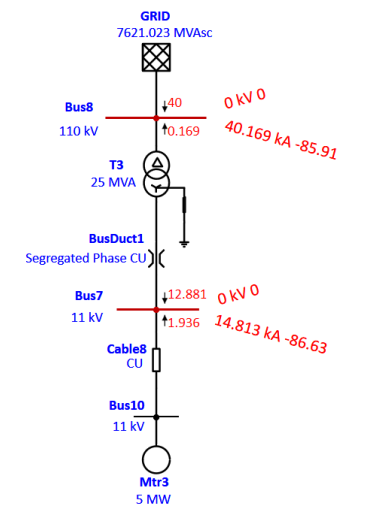
Validating with ETAP Results:
Three phase Fault:
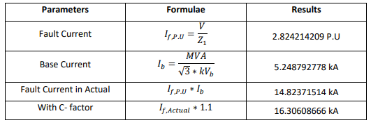
Single Line to Ground Fault:
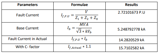
Line to Line Fault:

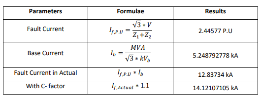
Double Line to Ground Fault:
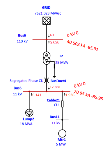
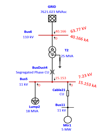
Case 3: With Motor load & Lump Load
Motor Ratings: 5 MW, 3-ph Induction Motor with 90% Eff, 95% P.F, X/R = 10.825, 𝑋′′ = 15.319
Lump Load: 18 MVA, 85% P.F, X/R =10, Constant Power Load

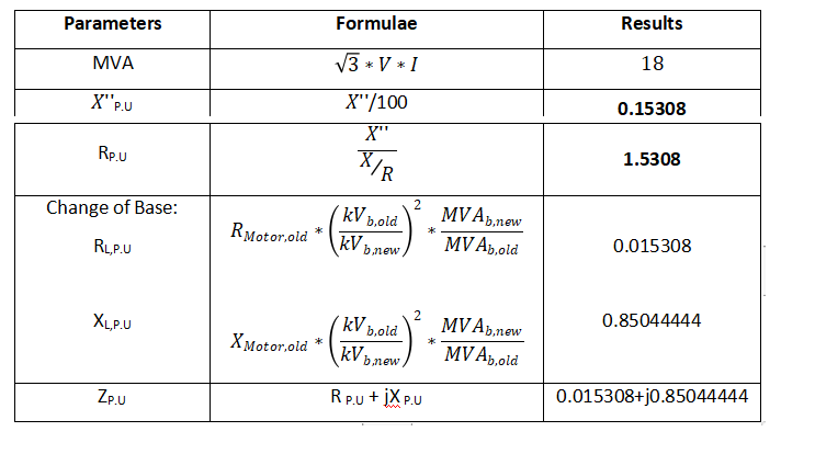
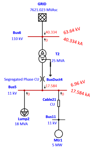
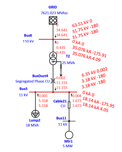
Validating Results with ETAP:
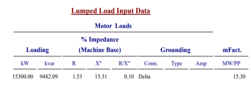
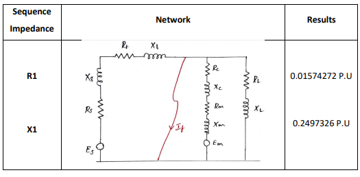
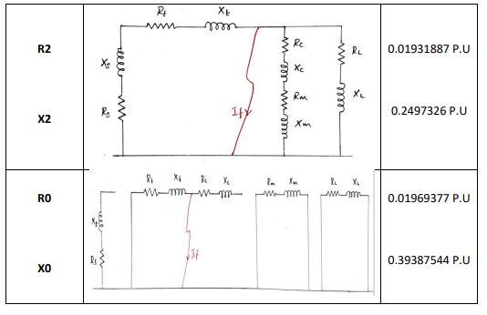
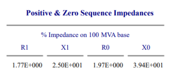
Validating with ETAP Results:
Three Phase Fault:
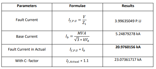
Single Line to Ground Fault:
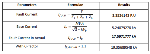
Line to Line Fault:
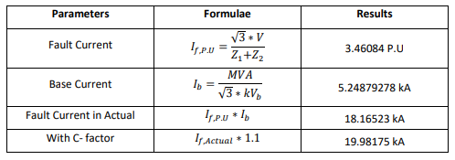
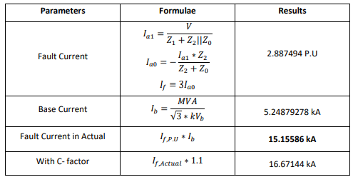
Double Line to Ground Fault:







in case 2 what is the value for NER
Excellent work. Thank you. Small correction: Effect C factor on Source impedance has to be taken in to account.
Very useful. Thank you. Small correction: Effect C factor on Source impedance has to be taken in to account.
Please let me know how this value is calculated:-
Fault current Ifpu =V / Z1 =2.454069 p.u
I appreciate you for this tremendous work.
Excellent explanation! Simple and clear. Thank you for sharing!
Awesome Thanks very much
Very useful.Thanks
super sir
how you got the value of cmax in the transformer short circuit…
how you got that cmax value in transfomer short circuit transformer part
Very useful & basic information.. thanks Abdul!
Simple n Stable Tabulation…!
fantastic work you’re doing
very effective, thanks
Wow Nice work..Mr.Abdul…
Awesome