OBJECTIVE:
The main objective of the blog is to find out different system grounding methods by using zero sequence X&R.
INTRODUCTION:
Grounding can be classified as Equipment grounding & System grounding. Equipment grounding is used for safety of human beings by minimizing the risk of electric shock. System grounding is used for connecting the Generator or Transformer neutral to provide
current return path during normal & faulted condition.
The system grounding consists of the following methods like
- Solid grounding
- Resistance grounding
- Reactance grounding
- Peterson coil (arc suppression coil) grounding
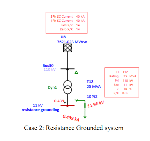
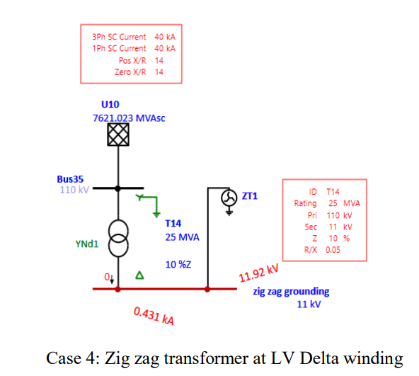
In this study we are going to compare the 25 MVA ,110/11 kV Delta-Star transformer with different LV grounding system like Solid grounding, Resistance grounding, Reactance grounding and 25 MVA ,110/11 kV Star-Delta transformer with Zig zag transformer on LV side.
APPLICABLE STANDARD:
FOR SHORT CIRCUIT CALCULATIONS
- IEC 60909-0: 2016 Calculation of Current
FOR EARTHING
- IEEE 80
- BS 7430
- IS 3043
- IEC 60364
FOR TRANSFORMER
- IEC 60076
INPUT SYSTEM DATA:
Grid Short circuit level for 3 phase & 1 phase is = 40kA
Grid X/R for 3 phase & 1 phase is = 14
Transformer positive sequence & zero sequence %Z is = 10
Transformer positive sequence & zero sequence X/R is = 20
Zig zag Transformer X/R is = 40
Single line to ground fault current is limited to 400 Amps when LV side is grounded using resistance, reactance or zig zag transformer.


SIMULATION REPORT:
OBSERVATION:
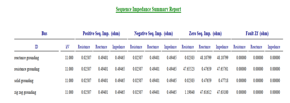
The values presented in below table are obtained from simulation software sequence impedance summary report.
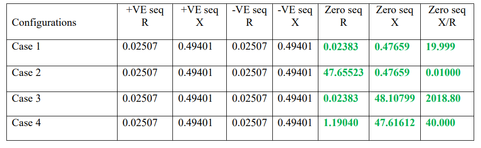
From case 1, it is observed that zero sequence “R” & “X” is almost equal to the positive & negative sequence “R” & “X” values. Hence, we can say this system is solidly grounded.
From case 2, it is observed that zero sequence “R” value is much higher than the “X” value. Hence, we can say this system is resistance grounded. It is also observed that Zero Sequence X/R is 0.0100 which is reduced (w.r.t. case 1 X/R ratio) due to increase in zero sequence “R” value.
From case 3, it is observed that zero sequence “X” value is much higher than the “R” value. Hence, we can say this system is reactance grounded. It is also observed that Zero Sequence X/R is 2018.80 which is increased (w.r.t. case 1 X/R ratio) due to increase in zero sequence “X” value.
From case 4, when system is grounded using zig zag transformer it is observed that zero sequence “X” value is much higher than the “R” value. It is also observed that due to zig zag transformer winding resistance, zero sequence “R” value is higher than the case 3 “R” value.
INFERENCE:
From the above observation it can be inferred that, the type of grounding can be determined by observing the values of zero sequence X and R. It is also observed that zero sequence X/R changes with respect to different grounding systems.


how to calculate Grid X/ R ratio ?
Really a different look which is so much useful.
MAGNIFICIENT ARTICLES
Very Useful Article. In one of my project when we have tie in feeder from upstream utility substiaon then my power system engineer was asking me following thigs for his further study.
1) X/R value of upstrem system
2) Fault level
Fault level was easily available through feed docuemtent but we could not able to guess type of earthing at upstream as fault level.In case 2,3 and 4 are h Soaving approximately same fault level. So, we raised TQ and asked X/R ratio of upstrem system to guess upstream earthing system.
But there I want to rasie one question , If we have upstream failt level ( lets say 400 A) then system grounding information genrally whre we used for system studies.