1.Introduction
- As the name implies, capacitor bank is merely a grouping of several capacitor. It may be connected in series or parallel depending upon the required rating.
- Increase in the number of capacitors in a bank will increase the energy storage capacity of the bank.
- The intent of this document is to explain about the capacitor bank sizing calculation and power factor correction.
2. Purpose
- Capacitor banks are used in power factor improvement and correction to eliminate reactive components at load side.
- They are also used to regulate the voltage of the system.
3. Advantages of using capacitor bank
- Reduction of electricity cost.
- Avoid penalty on utility bills.
- Increased transformer and generator capacity.
4 Calculation
Consider one 250 kW motor feeder in figure-1 and due to inductive load the power factor comes down, causing an increase in the reactive power.
Before selecting the capacitor bank the following points need to be noted,
- What is the desired power factor to be maintained at billing end.
- What is the required rating of capacitor bank.
- Where the capacitor bank needs to be located.
Formula used for sizing the capacitor bank
![]()

4.1 Sample calculation
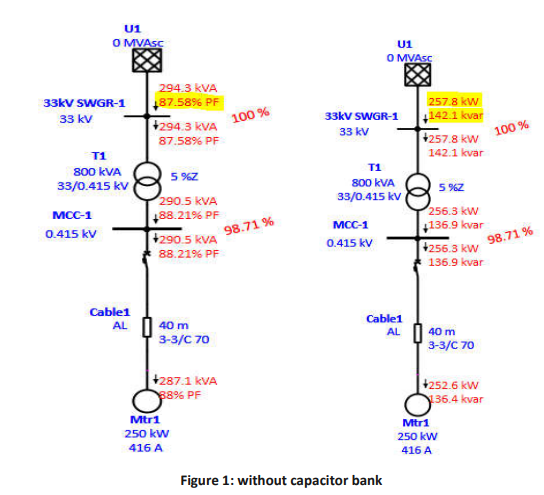
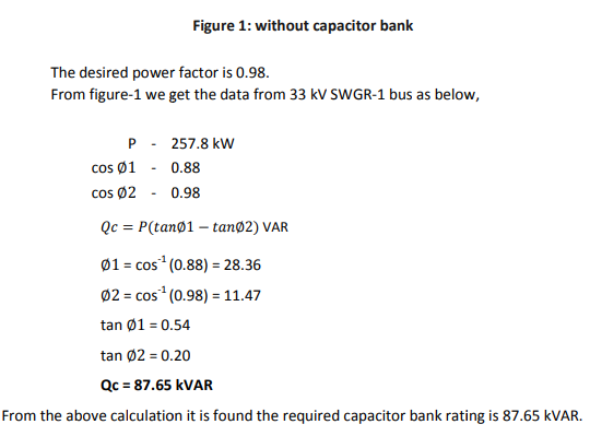
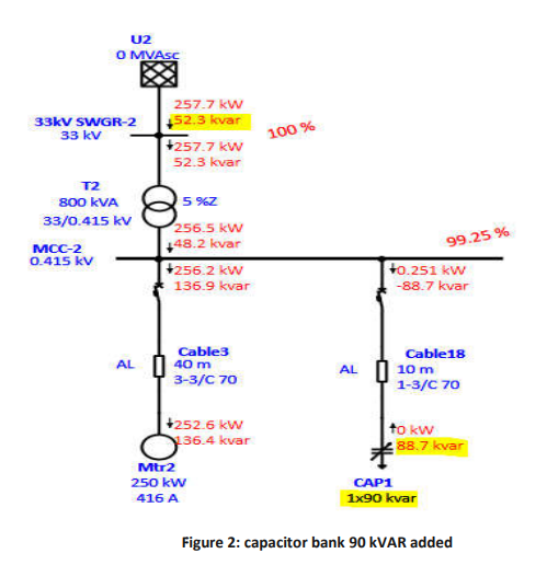
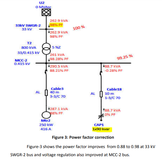
Figure-2 shows the reactive power compensated by adding switchable capacitor bank in parallel. The required rating of the capacitor bank is 87.65 kVAR. So here we have added 90 kVAR capacitor bank.
The reactive power supplied by capacitor bank is 88.7 kVAR.
5. Location of capacitor bank in LV system
The capacitor bank must be connected close to load in parallel with each phase of the load.
6. Conclusion
- Capacitor bank can be used to improve factor and regulate the voltage.
- Capacitor bank sizing depends on the power factor to be improve.
Nirmalraj Rengasamy
– Power System Engineer



Capacitor bank has to be connected to all phases of the supply or to only one phase ?
Good explanation sir
If P is in kW then Qc will be in kVAR