TRANSFORMER PROTECTION TRAINING
Join our comprehensive training that focuses on Transformer protection covering Transformer differential, restricted earth fault, overcurrent and earth fault protection, Overfluxing protection, Voltage protection and other necessary protection.
The failure of a transformer can be caused by any of several internal or external conditions that make the unit incapable of performing its proper function electrically or mechanically. Transformer failures may be grouped by initiating cause as follows:
a) Winding breakdown
b) Terminal boards and no-load tap changers
c) Bushing failures
d) Load-tap-changer failures
e) Miscellaneous failures
The principle relays and systems used for transformer protection:
(i) Buchholz device – Providing protection against all kinds of incipient faults.
(ii) Overcurrent relays – Providing protection mainly against phase-to-phase faults
and overloading.
(iii) Earth fault relays – Providing protection against earth faults.
(iv) Differential System – Providing Protection against both earth and phase faults.
(v) Harmonic Restraint and Harmonic Blocking.
This document covers the Overcurrent and Earth Fault Protection of Transformer.
Overcurrent Protection of the Transformer
Two relays are used to provide the overcurrent protection for the Transformer.
1. 51 IDMT (AC Time Inverse Overcurrent Relay) (51P& 51N)
2. 50 Instantaneous Overcurrent Relay (50P & 50N)
Let us discuss about Phase protection first (i.e) 51P and 50P
1. 51 IDMT (AC Time Inverse Overcurrent Relay) for Phase Protection
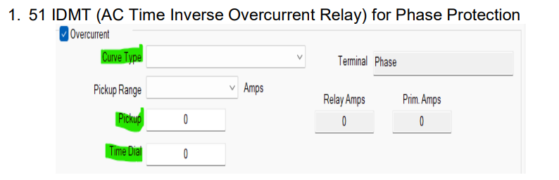
51 IDMT relay settings three inputs are required,
- Pick up (I>)
- Curve
- TDS/TMS (Time Dial Settings/ Time Multiplier Setting)
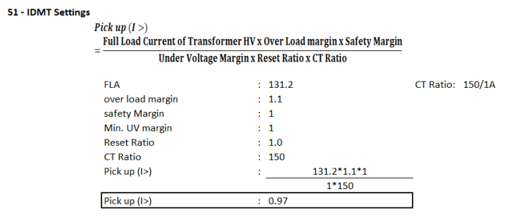
How to give the Pickup (I>) setting?
The relay should allow the normal current to the equipment as well as the overload up to a certain percentage required. The value of (I>) should be more than the allowable maximum load current as well as sensitive enough to respond to the minimum short circuit fault current.

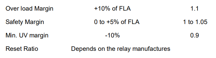
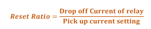
Where, reset ratio is per unit value of the pickup current below which the relay resets the Timer.
For Example,
FLA of Trafo: 90A, Micom P series relay is deployed for the overcurrent protection of Trafo.
Pickup current: 100A
Time Dial: 200 ms
If relay senses the current 100A, it starts the timer to give trip signal to the CB at 200ms of time delay. Whereas if the current becomes to FLA before 200ms the relay should not trip the CB, and It must reset the timer. A which current the relay must reset the timer is dictated by the relay manufacturers. This Micom P series relay has the reset value of 0.95. It means the relay resets the timer at (0.95×100=0.95A).
NOTE: “Generally, inclusion or exclusion of the reset ratio for the relay settings decided by the protection engineers. It is not necessarily to be added for all the cases. And the same applicable for over voltage margin and under voltage margin as well. Either over voltage margin or under voltage margin is considered to avoid too higher settings of Trafo HV side over current protection.” If over load Margin only considered for the calculation and reset ratio to be ignored. The formula for the pick-up settings could become,

Curve:
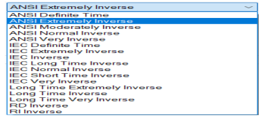
There are plenty of curves are available for 51 IDMT settings. The curve should be selected in the perfect way that, characteristics of the curve should not be affect the damage curves of the
equipment, Inrush current, downstream and upstream protection settings.
Which means, curve should fit into,
- Above the inrush Current of transformer.
- Above the LV Relay or release settings.
- Below the transformer damage curve.
For the HV side of the transformers IEC Extremely inverse / Long time Inverse curve is the better choice to fulfil the above requirement. And if the LV side of the Trafo have the LVCB with release settings, characteristics of LT setting is Extremely Inverse. So, it is recommended to choose IEC Extremely inverse curve.
How to give TDS/TMS (T>) setting?
TDS/TMS: Time Dial Settings/ Time Multiplier Setting
While making decision to give TDS setting, two things should be kept in mind that. The relay is the primary protection for the equipment as well as the backup protection for the downstream relay settings. And it must maintain the clear discrimination with the downstream settings. (i.e) the operating time of the primary relay should be less than that of the backup relay.
To comply the above philosophy, the procedure would be to start the relay/release setting from the tail end of the system. The relay at the tail end could be deployed to operate without any time delay. (i.e) Instantaneous settings without any intentional time delay. Backup relay could be given with intentional time delay settings.
TDS should be selected to ensure that operating time for through fault current is more than LV protection time and it should trip before the transformer damage. It must
ensure the Overloading capability of equipment’s are not compromised
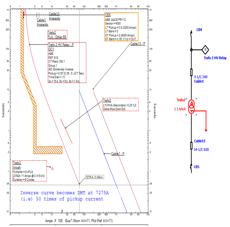
Above TCC graph shows that the 51-IDMT settings of the Trafo 2 HV relay. It is clear from the TCC graph that the settings are above the Inrush characteristics, below the Damage curve of the Transformer and coordinated with the LV release settings of the CB5.
50 Instantaneous Overcurrent protection for phase
Two inputs are required for the 50 settings.
- Pick up (I>>)
- Time delay (T>>)
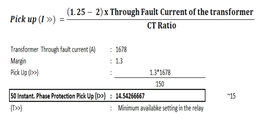
How to give Pick up (I>>)?
(I>>) Should be set to pick up at value higher than the maximum asymmetrical through fault current. Through fault current is nothing but the fault current through the transformer for a three-phase bolted fault at LV side of the Transformer. A pickup setting would be 125% to 200% of the symmetrical through fault current, with consideration of the presence of the DC decaying component in the asymmetrical fault current as well as CT error, Relay Error and impedance variation of the transformer with respect to the tap changers.

(I>>) value should be higher than the inrush current to avoid the nuisance tripping. Selection of the margin value between (1.25 to 2) is depends on the ratio of asymmetrical current to symmetrical current. If that value is higher, then the margin may set at maximum. The ratio of asymmetrical current to the symmetrical current is directly proportional to the value of (X/R). In simple terms if X/R value is high it is necessary to give higher margin.
Low voltage transformers have lower X/R value, so margin could be selected as 1.30.
How to give Time Delay(I>>) settings?
The minimum available time setting must be given as (I>>). (i.e) Intentional time delay should not be given as (I>>) because if intentional time delay is introduced then these 50 relays behaves as a 51 relay.
Below figure shows the TCC curve of the transformer protection with the setting of the two stages 51 Overcurrent and 50Instantaneous. There is some unnecessary time delay between the LV release and the Trafo2 HV relay as marked in GREEN. to avoid the time delay in the operation of the relay, another Definite time stage could be introduced in between the above two stages.
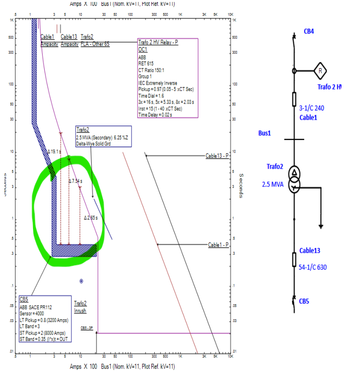
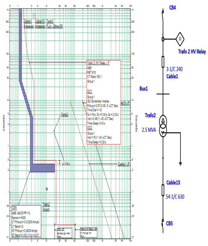
It is clear that introduction of the DMT stage in between IDMT and Instantaneous stages helps to reduce the fault clearing much further and it has the coordination with the downstream as well
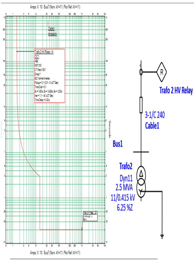
51N and 50N settings:
51N and 50N gives protects the transformer against the earth fault.
How to give 51N settings?
Like 51P, 51N also requires three inputs
- Pickup (Ie>)
- Curve
- Time Dial Setting
How to give Pickup (Ie>) setting?

10% of the full load current should be given as the Pickup setting.
How to select the curve? Generally Normal Inverse curve is preferred for the 51N settings.
How to select TDS settings (Te>)? TDS should be given as a minimum possible time and it should be ensured that the relay should not mal operate during the energization of the Transformer. 0.1s could be set as a TDS
How to give 50N (Ie>>) settings?
It gives the instantaneous protection against the earth fault of the transformer.
![]()
F.L.A could be given as the pickup setting.
How to give TDS settings (Te>>)?
The minimum available time setting must be given as (I>>). (i.e) Intentional time delay should not be given as (Te>>), 0.02 could be given as as TDS for 50N.
NOTE:
Because of the absence of the Zero sequence components in Delta side of the Trafo. This 51N and 50N really don’t need to be coordinated with the downstream LV release settings. And it should be noted that if there is any upstream relay in the Transformer’s feeder. That needs to be coordinated with this 51N and 50N
Highly useful knowledge material. Only one observation, the use of term ” no-load tap changer” may provide the indication that the Tap Changer may be operated under no load condition(e.g. A typical distribution Transformer with energized high voltage side but no ” load current ” drawn from the low voltage side). In such case one may safely use the well recognized terminology as ” Deenergized tap Changer”.