Power system supply or consumes both active and reactive power. While it is the Active power that contributes to the energy consumed or transmitted, reactive power does not contribute to the energy. Reactive power is either generated or consumed in almost every component of the system. Reactive power compensation is defined as the management of reactive power to improve the performance of AC systems.
Why reactive power compensation is required?
1. To maintain the voltage profile
2. To reduce the equipment loading
3. To reduce the losses
4. To economics
There are two aspects to reactive power compensation
1) Load compensation
The main objective of the load compensation is to increase the power factor of the system, to balance the real power drawn from the system, to compensate
voltage regulations.
2) Voltage support
The main purpose is to decrease the voltage fluctuation at a given terminal of transmission line. Therefore the reactive power compensation improves the
stability of AC system.
What is Reactive power?
Reactive power is the portion of electricity that establishes and sustains the electric and magnetic fields of alternating current equipment. Reactive power must supplied to most types of magnetic equipment, such as motors, Transformers, etc.
Methods of Reactive power compensation:
- Synchronous condensers
- Static VAR Compensators
- Static synchronous compensators(STATCOM)
- Series compensation
Having said the types of compensation, in this article we are going to discuss mainly about Shunt compensation using Capacitor bank.
Since most loads are inductive in nature they consume lagging reactive power, so the compensation required is usually shunt capacitor bank.
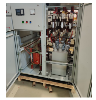
Shunt Capacitor Banks
Shunt capacitors are employed at substation level for the following reasons:
- Reducing power losses: Compensating the load’s lagging power factor with the bus connected shunt capacitor bank improves the power factor and reduces
current flow through the transmission lines, transformers, generators, etc. This will reduce power losses in the equipment, cables and transmission lines. - Increased utilization of equipment: Shunt compensations with capacitor banks reduces kVA loading of lines, Transformers, and Generators, which
means with compensation they can be used for delivering more power without overloading the equipment. Shunt compensation can be installed near the load, in a distribution substations and along the distribution feeder. - It improves the power factor of the source current
- It reduces capital investment per megawatt of the load
We will validate a reactive power compensation using shunt capacitor bank by modelling a sample power system network using DIGSILENT Powerfactory
software. Following network consists of single grid, 1 MVA 11/0.4 kV Transformer connected to 800 kVA load with the power factor of 0.85.
Network without Capacitor Bank

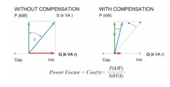
In above picture we can observe in the highlighted region that power factor is 0.839 Lagging in the HV side of the transformer. In order to Improve the power factor to desired power factor of 0.95. We need Additional capacitor bank. So in order to calculate reactive power required (capacitor bank rating) following formula and calculations is used
![]()
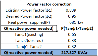
From above table calculation, reactive power need is 217.8 kvar. So we need connect 217.8 kvar capacitor bank at load bus.
Network with capacitor bank

From above picture we can conclude that after connecting 217.8 kvar capacitor bank at the load terminal. Power factor at the high voltage side of the transformer
(highlighted region) has significantly improved from 0.839 power factor to 0.95 power factor (desired power factor).
Conclusion:
Use of capacitive (shunt compensation) on various part of the power system improves power factor, Reduce power losses, improves voltage regulation and increased utilization of equipment.
Reference: Electric power generation, Transmission and distribution by Leonard L.Grigsby.
it is very much useful to Electrical Engineer
Hi Sir.
Why the cap installed at load instead of the vus where wr need it?
Hi Sir.
Why the cap installed at load instead of the vus where wr need it?