CEA Guidelines for Generic RMS Modelling of Wind Generating Stations
A missing control function can mean another round of model revisions when your study deadline is close. Before sharing a wind-farm RMS model, check whether its structure represents the installed turbine technology and the plant controls you need to assess.
GRID-INDIA’s guidance groups generic wind models by turbine type and explains which converter and controller models are suitable. This article explains those selections and the data you should agree with your OEM and study team.
Generic RMS models represent the fundamental-frequency electrical response and relevant control dynamics. Their parameters must be matched to the equipment and operating mode being studied.
Start with the wind turbine technology
Type | Technology | Main modelling functions |
|---|---|---|
Type 1 | Direct-connected squirrel-cage induction generator with fixed-speed operation | Induction generator and drive train, with pitch control for active-stall designs |
Type 2 | Wound-rotor induction generator with variable external rotor resistance | Generator, rotor-resistance control, drive train and pitch control |
Type 3 | Doubly fed induction generator with a rotor-side converter | Converter interface, electrical controls, mechanical dynamics and plant control |
Type 4 | Full-converter wind turbine, including synchronous and permanent-magnet designs | Converter interface, electrical controls, plant control and applicable drive-train dynamics |
The technology determines the model structure. A change in the turbine rating alone does not establish that a different technology’s model can represent it.
Represent Type 1 and Type 2 machines
For Type 1, the guidance lists WT1G_ for the induction generator and wt1p_b for pitch control where active stall is used. For Type 2, WT2G_ represents the generator and WT2E1 represents the external rotor-resistance controller. Mechanical and pitch-control blocks complete the relevant configuration.
Check software-specific names before building the case. The extract labels the Type-1 drive-train model WT2T1, while the documented PSS®E name is WT12T1 for both Type 1 and Type 2. WECC also lists WT12A1U_B as the PSS®E equivalent of WT1P_B from version 34 onwards. The extract’s statement that no PSS®E equivalent exists should therefore be checked against your installed version.
Separate the model functions for Type 3 and Type 4
For converter-based turbines, select the generator interface, electrical controller and plant controller as separate functions. The following mapping summarises the model roles in the guidance and clarifies the aerodynamic model’s name.
Function | Model |
|---|---|
Generator and converter interface | REGC_ |
Electrical controls at turbine level | REEC_ |
Drive-train dynamics | WTDTA1 |
Type-3 aerodynamic response | WTARA in the extract, with PSS®E variants WTARA1 and WTARAU1 |
Type-3 pitch control | WTPTA1 |
Type-3 torque control | WTTQA1 |
Plant-level control | Applicable REPC_, PLNTB_ or HPLNTDU model |
Type 3 combines the electrical blocks with the relevant aerodynamic, pitch, torque and drive-train models. For Type 4, include mechanical dynamics only as supported by the model and needed to represent the turbine response. Confirm how the selected plant controller passes commands to the turbine controls.
The Type-4 table in the extract repeats PLNTB_ and HPLNTDU beside the electrical-control entry. In the functional mapping above, these are treated as plant-controller options. They do not replace the turbine electrical-control function represented by REEC_.
Three model selection recommendations
REGC_B and REGC_C are preferred over REGC_A in the shared guidance. Their voltage-source interfaces improve numerical behaviour in weaker networks. REGC_C also represents the inner current-control loops and phase-locked loop, or PLL. A numerically stable run still needs validation against the equipment response.
REEC_B is not recommended because its simplified structure omits voltage-dependent inverter current limits. Select an electrical-control model that represents the OEM’s current limits and priority logic. During a voltage disturbance, these settings influence how the available current is divided between active and reactive output.
REPC_A is not recommended in the shared guidance because it lacks plant-level constant power-factor control. If your study includes this mode, select a supported controller that can reproduce it. For example, holding a fixed MVAr reference while active power changes do not maintain a fixed power factor.
These recommendations concern different parts of the model. Changing the REGC interface does not add a missing function to the electrical controller or plant controller. Check the complete combination and its control settings.
Grid Forming Models
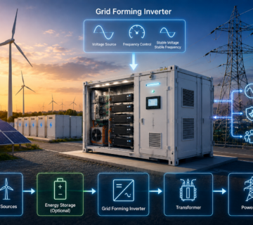
For Type-4 turbines operating with grid-forming controls, the guidance lists REGFM_A1 and REGFM_B1 for the combined generator and electrical-control representation. Their control strategies differ.
Model | Control strategy |
|---|---|
REGFM_A1 | Droop-based grid-forming control |
REGFM_B1 | Virtual synchronous machine control |
The extract also lists plant-controller options and WTDTA1 for drive-train dynamics. Confirm that these interfaces are supported by the selected model implementation. A Type-4 turbine’s full converter does not by itself establish grid-forming capability. The implemented control strategy must support that operation.
REGC_B and REGC_C use voltage-source network interfaces, but that interface choice alone does not make them grid-forming models. Select REGFM models when their control behaviour matches the OEM equipment.
Exchange the data needed to reproduce the study
As a practical handover checklist, agree the following information with your OEM and study team. This supports model use alongside the project’s applicable submission requirements.
- Identify the turbine type, rated MW and MVA, voltage base, unit count and aggregation method.
- State the simulation software version, exact model names, model revisions and required supporting files.
- Provide the parameter set, control-mode flags, P and Q limits, current limits, droop settings and documented protection behaviour.
- Define the plant-controller connections, command and feedback signals, measurement locations, sign conventions, per-unit bases and represented delays.
- Include the collector-system and transformer representation, operating points, test settings, reference responses and known model limitations.
Before handover, confirm stable initialisation and run the applicable active-power, reactive-power, voltage, frequency and fault-response tests. Compare results at the same measurement point, using matching bases and initial conditions. Record any mismatch and its effect on the intended study.
When you share your wind-plant model, can another engineer reproduce the intended control modes and test results using the files and instructions you provide?