
PID Controller in Power Plant Controller (PPC)
PID (proportional-integral-derivative) controller is a control system based on a closed-loop feedback control system and has already been widely used in the power sector, power industry, etc. It works by means of output voltage and output power for an industrial control system.
In This Article
What is a PID controller
What is a PID controller PID (proportional-integral-derivative) controller is a control system based on a closed-loop feedback control system and has already been widely used in the power sector, power industry, etc. It works by means of output voltage and output power for an industrial control system. Its principle is to control output voltage/power to achieve the purpose of reducing the voltage difference between actual power generation (measured value) and voltage/power target (reference value).
where:
- 𝒆(𝒕) = Control error
- 𝒓(𝒕) = Reference or setpoint
- 𝒚(𝒕) = Measured process value
The control output of a PID controller is determined using the following equation:
Proportional (P)
The output is proportional to the current error, so this component instantly adjusts to disturbances.
Integral (I)
The output integrates the error over time, which ensures that any remaining error is eliminated and the process reaches the reference (setpoint).
Derivative (D)
The output is proportional to the rate of change of the error. This helps to damp down the system and reduces overshoot.
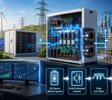
Within a Power Plant Controller (PPC), these signals from the Point of Interconnection (POI) are constantly read by the PPC's PID controller, compared to the plant setpoints and correct signals sent to the plant inverters or Battery Energy Storage System (BESS). The renewable energy plant continues to supply a stable voltage, with accurate active and reactive power controls that can maintain compliance with Grid Code requirements under both normal and fault scenarios. However, many commercial solar and BESS Plant Controllers opt for PI controllers for voltage/reactive control, where more dynamic operation than expected under the norm due to the noise sensitivity of the differential factor.

How the PID works in PPC
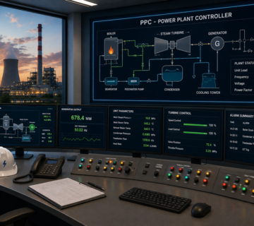
The role of a power plant controller (PPC). The power plant controller (PPC) is the supervisory control and coordination system of all inverters and energy resources in a power plant. Its principal duty is to guarantee compliance with grid operator setpoints for plant active power output (MW) and voltage, power factor, and reactive power (MVAr), and for regulation of voltage and power at the POI during stable power plant operation.
How a PPC implements PID: The PID controller (at the heart of the decision-making element in a PPC) acts by continuously comparing the required reference output value, SP, set by the grid operator, with the actual measurement M value available at the POI. The difference 𝐞(𝒕) = Setpoint − the setpoint value called the error is applied by the PID algorithm. The PPC uses the calculated error together with the proportional, integral and derivative output actions to come up with an output that is communicated as control setpoints to all interconnected inverters / BESS converters.
For instance, if the measured voltage at the POI is lower than that specified in the set point, the system will detect a positive error, which means that reactive power has to be added to the grid by all inverters and thus injected. By gradually decreasing this reactive power set point to zero, the voltage at the POI approaches the reference voltage value smoothly without the overshoot generated with less effective controllers. On the reverse, should the measured voltage be higher than the set point, the additional negative reactive set point injected in the system causes voltage reduction up to the set point. The same applies to plant active power. When the grid operator calls out to adjust the overall generation from the plant, the plant manager would ask it to set its reference values as requested by the operator; the same controller would compare the needed plant generation to the current plant power delivered and adjust its inverter accordingly.

Impact of PID on Grid Stability
Grid Parameter | Without PID | With PID |
|---|---|---|
Voltage | Large fluctuations | Stable voltage |
Reactive Power | Oscillations | Smooth MVAr control |
Active Power | Sudden changes | Controlled ramping |
Frequency Support | Slow | Faster response |
Grid Code Compliance | Difficult | Achieved |

A PID controller serves a fundamental aspect of the Power Plant Controller (PPC) to allow a renewable energy plant (REP) to operate stably under diverse grid operating environments and supply consistent power. By consistently comparing the referenced setpoint value with the measured setpoint value from the Point of Interconnection (POI), a PID controller produces an adequate control signal to command the plant inverter to control the active power, the reactive power, voltage, power factor, etc. Through the plant inverters.
The resulting feedback loop system with the PID control mechanism helps to trace correctly operating reference setpoint and minimise the steady-state errors while enhancing the response during disturbance conditions of the plant.
In most solar and/or Battery Energy Storage System (BESS) plant designs and applications, the PI (Proportional-Integral) algorithm, being simple and effective, is usually applied as the controller, but derivatives are applicable only for special usage requirements of system dynamics enhancement. Thus, an efficient PID controller plays a central function for achieving grid code compliance, power quality, as well as stable interconnection of renewable energy resources.
)