TRANSFORMER X/R RATIO – EFFECT ON INSTANTANEOUS OVER CURRENT SETTING FOR TRANSFORMER HIGH VOLTAGE SIDE RELAY
Transformer X/R ratio affects the Instantaneous over current (IOC) (ANSI code 50) setting of transformer high voltage side relay. This happens due to asymmetrical nature of the fault current at the instant when the relay interrupts the fault current. Thus understanding the nature of asymmetrical fault current is essential.
ASYMMETRICAL FAULT CURRENT:

Refer Transformer X/R ratio Video
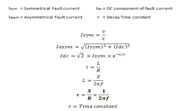
Figure 1 shows a typical fault in an AC system. From the illustration it can be seen that there is an initial DC current component (IDC). This initial DC component decays over time, eventually reaching zero. Addition of the DC component to the symmetrical short circuit current gives the asymmetrical fault current.

From above equations it can be noted that DC current (IDC) component decays exponentially and its decay depends on the X/R ratio (Time constant) of the system. Hence the magnitude of DC current component is based upon two scenarios:
1. At what voltage angle, the fault is happening
With respect to voltage and current waveforms, since the power system is a RL circuit, it consists of both inductance and resistance. However the power system is generally considered to be inductive in nature. Current in inductance cannot change instantaneously. When a fault occurs at voltage angle zero degree, then current is Maximum and current can’t change instantaneously, so DC component comes into existence. So the waveform will be offset for first few cycles. If fault occurs at voltage angle of ninety degrees, then there won’t be a presence of DC current component.
2. What is the X/R Ratio at the time of fault?
It determines the duration of the DC current component
X/R Ratio does not impact the RMS fault current but it will impact the Peak current. Increase in X/R Ratio will increase the peak current.
If DC current component decays, then Asymmetrical fault current becomes Symmetrical fault current. If X/R ratio is higher, DC current component takes longer time to decay and causes transient over reach.
EFFECT of X/R on Instantaneous Over Current Protection Setting
In Transformer protection, a transformer with higher X/R ratio causes transient overreach. The instantaneous over-current relay operates as soon as the value of current exceeds the set value. Even though this high current may be only for few cycles. When a fault occurs, DC component is introduced in the current wave which decays slowly due to higher X/R ratio. The relay may mal-operate
due to this DC offset current. Thus, if the fault occurs outside the assigned zone of the relay, it may send an unwanted trip signal to the circuit breaker. When using instantaneous over current protection, Care must be exercised in choosing the settings to prevent them operating for faults beyond the protected zone especially when transformer X/R ratio is higher causing Transient overreach. This statement is clearly emphasized in IEEE 242 standard
IEEE 242 11.9.2.2.3.2 (Transformer protection: Instantaneous over current relays) states that “Phase instantaneous over current relays provides short circuit protections to the transformers in addition to over load protection. When used on the primary side, they usually coordinate with secondary protective devices. Fast clearing of severe internal faults can be obtained. The setting of an instantaneous relay is selected on its application with respect to secondary protective devices and circuit arrangements. Such relays are normally set to pick up at a value higher than the maximum asymmetrical through-fault current. This value is usually the fault current through the transformer for a low-side three phase fault. The setting of instantaneous devices for short circuit protection for three-circuit arrangements is described in Mathur [B21]. For instantaneous units subject to transient overreach, a pickup setting of 175% of the calculated maximum low-side three-phase symmetrical fault current generally provides sufficient margin to avoid false tripping for a low side bus fault, While still providing protection for severe internal faults. (Variations in pickup settings of 125% to 200% are common) For instantaneous units with negligible transient overreach, a lesser margin can be used. The setting in either case shall-also be above the transformer inrush current to prevent nuisance tripping. In some cases, Instantaneous trip relays cannot be used because the necessary settings are greater than the available fault current. In these cases, a harmonic restraint instantaneous relay may be considered to provide the desired protection.”
The following cases are simulated in ETAP 19.0.1 to visualize how the transformer X/R ratio affects the instantaneous over current setting (ANSI code 50) of transformer HV Side relay.
Case 1: 2.5 MVA Transformer with X/R = 3.5


In this case 1: 2.5 MVA Transformer has X/R ratio of 3.5. From Figure 2 it is observe that at exactly 20 milliseconds (Time at which instantaneous relay operates) there is a little difference between IB symmetrical fault current (50.954 kA) and IB asymmetrical fault current (53.303 kA). DC current component (IDC) (15.652 kA) takes lesser time to decay due to lower X/R ratio (negligible transient overreach) so for Instantaneous over current setting (50) (Transformer HV relay) extra 130% margin of through fault current can be
given. Setting can be calculated using the formula below

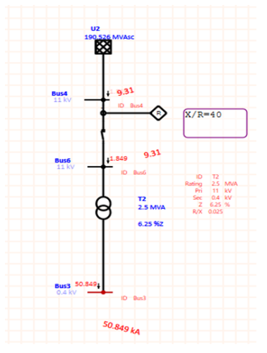
Case 2: 2.5 MVA Transformer with X/R = 40


In this case 2: 2.5 MVA Transformer has X/R ratio of 40. From Figure 3 it is observe that at exactly 20 milliseconds (Time at which instantaneous relay operates) there is a huge difference between IB symmetrical fault current (50.849 kA) and IB asymmetrical fault current (77.200 kA). DC current component (IDC) (58.088 kA) takes more time to decay due to higher X/R ratio (Transient overreach)
So for Instantaneous over current setting (50) (Transformer HV relay) extra 175% margin of through fault current can be given (as per IEEE 242).This generally provides sufficient margin to avoid false tripping for a low side bus fault, While still providing protection for severe internal faults. Setting can be calculated using the formula below

Conclusion:
If Transformer X/R ratio is high, we have to give significant margin (175% as per IEEE 242) of through fault current for Instantaneous over current (50) relay setting of transformer High Voltage side relay.

References:
IEEE 242-2001- Recommended Practice for Protection and Coordination of Industrial and commercial Power Systems.


No comment