TRANSFORMER PARALLELING:
Advantages:
- Load sharing
- Efficiency
- Redundancy
- Cost minimization
- Reliable power supply
Disadvantages:
- Increase the short circuit current that increase breaker capacity.
- Bus rating could be too high.
- Paralleling of transformers reduce the transformer impedance significantly.
Conditions for Transformer Paralleling:
- Transformer rating should be same.
- Polarities of the transformer should be same.
- Percentage impedance should be same.
- Ratios of (X/R) should be same.
- Phase angle should be same.
- Phase sequence of the transformer should be same.
- Frequency should be same.
- Tap changers should be same.
- Transformers vector should be same.
- Above few conditions check with different case in ETAP
Case (1): Transformer with Same Rating

Figure 1. Transformers with same rating
In case 1, Both the transformer ratings are same for parallel operation, By the results the 40 MVA load is equally shared by the Both transformers.
Case (2): Transformers with different MVA rating

Figure 2. Transformers with Different MVA
In case 2, For parallel operation both transformers are designed with different MVA rating. From the simulation results, the load is shared equally with equal ratio. Then its loading of the both transformers are equal. So different MVA rating of the transformer is not a problem in parallel operation of transformer. Two Transformer with difference up to 3 times can be paralleled.
Case (3): Transformer with Different Impedance

Figure:3 Transformers with Different Impedance
In case 3. Both of the transformer, load is not equally shared. Because lower impedance transformer is higher percentage of load compared to the higher
impedance of the transformer. We are not able to utilize transformer up to its full rating.
Sizing loads should be done with respect to lower impedance. Though not acceptable but transformer with impedance values which are close to each other can be parallel.
Then the transformer T6 is overloaded during parallel operation. So, the transformer with different impedance is not Suitable for parallel operation.
Case (4): Transformer with different voltage

Figure 4. Transformers with Different Voltage
In case 4, For parallel operation both transformers are designed with different Voltages, load is not equally shared. Because power shared transformer T9 is higher than the transformer T10.
Transformer with different voltage are not optimal to be parallel as they result in large circulating current. So, the transformer with different voltage is not Suitable for parallel operation.
Case (5): Transformer with Different Tap changer

Figure 5. Transformers with Different Tap changer
If tap change in LV side current will reduce and voltage is varied.
If manually change the tap in OLTC means master and slave concept is used. By this concept when the master transformer tap is changed from one position to another position the same condition is given to the slave transformer and the salve transformer tap is changed to the same position of the master transformer tap and it produce a huge circulating current.
In case 5, For parallel operation both transformers are designed with different Tap changer, load is not equally shared. Because power shared transformer T11 is higher than the transformer T12 and Power factor will not be same. So, the transformer with different voltage is not Suitable for parallel operation.
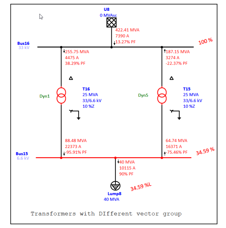
Case (6): Transformer with different vector group

Figure 6. Transformers with Different Vector Group
In case 6, For parallel operation both transformers are designed with different Vector group. Transformer T16 configures as Dyn1 and Transformer T15
configures as Dyn5.From simulation results, huge amount of circulating current flows in this condition.
Certain vector groups can be parallel,
- Group 1 can be parallel only within Group1.
- Group 2 can be parallel only within Group2.
- But Group 3 & Group 4 can be parallel with each other.

Case (7): Transformer with different X/R ratio

Figure 7. Transformers with Different X/R ratio
In case 7, For parallel operation both transformers are designed with different Vector group.
Transformer T1 configures as X/R ratio is 20 and Transformer T2 configures as X/R ratio is 40. From simulation results power factor is not equal and it directly depends on copper loss because when resistance is increased, the X/R ratio is reduced and Voltage group of the transformer is high in transformer T1 and low in T2. So, the transformer with different vector group is not suitable for parallel operation.


We have two transformers and they have different vectors YNd11 & YNa0d11. Can these two transfomers parallel?
Which tool you used for simulation of different scenerios?