
This article studies the role of transformer OLTC on reactive power flow in Power plant (Generator Step up Transformer) & Load center applications.
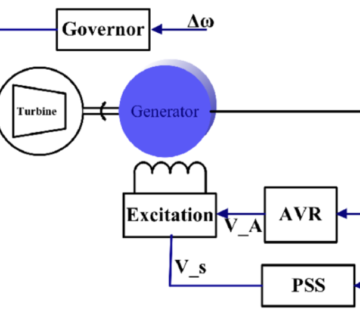
1. POWER PLANT
Power system equipment is designed to operate within specified tolerance of the nominal voltages. The tolerance ranges from 5 % to 10 % depending on the voltage level and equipment rating. The stability and reliability of the electrical power system depend on reactive power management. Fluctuations in voltage levels lead to the reduction in life of the various appliances. High voltage damages the insulation of windings whereas low voltage causes increased current (and hence heat) and poor performance of the various equipment like low illumination of bulbs, overheating of induction motors, etc.
CAUSES OF LOW VOLTAGE
“If the power demand is more than that supplied by transmitting lines, the current drawn from supply lines increases to a higher level which causes the voltage to fall drastically at the receiving end side. If the low voltage is decreased further, it leads to the tripping of generator units, overheating of motors and other equipment failures.”
CASE1: WITHOUT TRANSFORMER TAP CHANGER WHEN THE GRID VOLTAGE IS LESS
11 kV voltage is generated by using 100 MW generator. This voltage then stepped up to 220 kV through 125 MVA transformer. Transmission of that 220 kV is done by 50 km transmission line.
![]()
INFERENCE:
The maximum reactive power capability of the generator (Q Max) is 75 Mvar. But it generates 20.4 Mvar only. Due to more demand than the generation, the ‘220 kV Bus-1’ voltage is reduced to 98.24 % & the ‘220 kV Bus-2’ voltage is reduced to 97.5 %. By increasing the reactive power output from the generator, we can improve the voltage. For that, Transformer tap changer is provided on Generator step up transformer’s HV winding to regulate the LV voltage.
CASE2: WITH TRANSFORMER TAP CHANGER WHEN THE GRID VOLTAGE IS LESS
![]()
INFERENCE:
By increasing the transformer’s tap to 7.5 %, we extract the generator’s maximum reactive power (72.8 Mvar). So, the ‘220 kV Bus-1’ voltage is increased to 100 %. The ‘220 kV Bus-2’ is a slack bus. For understanding, consider the ‘220 kV Bus-1’ only.
CAUSES OF HIGH VOLTAGE
“If the power demand is less than reactive power supplied, the load voltage rises to a higher level which leads to automatic tripping of transmission equipment, low power factor, insulation failures of the cables, and windings for various mechanical devices.”
CASE3: WITHOUT TRANSFORMER TAP CHANGER WHEN GRID VOLTAGE IS HIGH
![]()
INFERENCE:
The minimum reactive power capability of the generator (Q Min) is -32 Mvar. But it absorbs -12.6 Mvar only. Due to less demand than the generation, the ‘220 kV Bus-1’ voltage is increased to 101.5 %. & the ‘220 kV Bus-2’ voltage is increased to 102 %. By decreasing the reactive power output from the generator, we can reduce the voltage. For that, Transformer tap changer is provided on Generator step up transformer’s HV winding to regulate the LV voltage.
CASE4: WITH TRANSFORMER TAP CHANGER WHEN GRID VOLTAGE IS HIGH
![]()
INFERENCE:
By decreasing the transformer’s tap to -2.5 %, we reduce the generator’s reactive power (-31.3 Mvar). So, the ‘220 kV Bus-1’ voltage is reduced to 100.8 %. The ‘220 kV Bus-2’ is a slack bus. For understanding, consider the ‘220 kV Bus-1’ only.
2. LOAD CENTER
Let’s consider, 110 kV gird feeds 11 kV load by using the transformer of 45 MVA. There is a fluctuation of grid voltage between +12.5 % to -12.5 %. Because of grid voltage fluctuation, the load varies from 10 kW to 38 kW. In this case, it is necessary to regulate the voltage within ±5 % at the load end. The voltage regulation can be done at the load end, by changing the transformer tap position at both positive and negative sides.
SELECTION OF TRANSFORMER TAP ON THE NEGATIVE SIDE
Following things need to be considered when we select the transformer tap on the negative side:
1. What is the minimum grid voltage?
2. What is the maximum possible load?
3. What is the poor power factor possible?
4. What is the minimum voltage allowed in the industry?
In our case,
1. Minimum grid voltage is 87.5 % (Normal grid voltage is 100 %. Due to fluctuation the
grid voltage will come down to 12.5 %. So, 100 % – 12.5 % = 87.5 %)
2. The maximum possible load is 38 kW
3. The power factor possible is 85 %
4. The minimum voltage allowed in the industry is ≥ 95 %
CASE 1: WITHOUT TRANSFORMER TAP
![]()
INFERENCE:
When the gird voltage comes to 87.5 %, the 11 kV bus voltage is 87.49 % (Under-voltage). To maintain the voltage within the limit at the 11 kV bus side (Load end), it is necessary to apply the tap changer on transformer’s HV winding to regulate the LV voltage.
![]()
INFERENCE:
By reducing the transformer’s tap to -10 %, the 11 kV bus voltage is increased to 97.22 %, even though the gird voltage comes to 87.5 %.
SELECTION OF TRANSFORMER TAP ON THE POSITIVE SIDE:
The following things need to be considered when we select the transformer tap on the positive side:
1. What is the maximum grid voltage?
2. What is the minimum possible load?
3. What is the best power factor possible?
4. What is the maximum voltage allowed in the industry?
In our case,
1. Maximum grid voltage is 112.5 % (Normal grid voltage is 100 %. Due to fluctuation
the grid voltage will goes to 12.5 %. So, 100 % + 12.5 % = 112.5 %)
2. The minimum possible load is 10 kW
3. The best power factor possible is 85 %
4. The maximum voltage allowed in the industry is ≤ 105 %
CASE 3: WITHOUT USING TRANSFORMER TAP
![]()
INFERENCE:
When the gird voltage goes to 112.5 %, the 11 kV bus voltage is 112.5 % (Over-voltage). To maintain the voltage within the limit at the 11 kV bus side (Load end), it is necessary to apply the tap changer on transformer’s HV winding to regulate the LV voltage.
CASE 4: WITH USING TRANSFORMER TAP
![]()
INFERENCE:
By increasing the transformer’s tap to 8.75 %, the 11 kV bus voltage is reduced to 103.4 %, even though the gird voltage goes to 112.5 %.
CONCLUSION:
From this article, it is concluded that the tap changer in the transformer can be used to regulate the voltage at the load end and it is also used to manage the reactive power flow at the power plant.
Saravana Kumar
– Power System Engineer

Please show connection diagram of OLTC with RTCC panel
Case studies are also teacher for knowledge acquiring platform…..thanks for your knowledge sharing… request you to share to my watsapp no or email