
Capability Curve of Generator
Capability Curve of Generator defines the boundaries within which it can deliver reactive power continuously without overheating.
Generator rating is specified in terms of MVA and power factor at a particular terminal voltage. Active power delivered by generator is only limited by the power delivering capability of turbine.
But the reactive power which a generator can deliver continuously without over heating is governed by three limits: Armature Current Limit, Field Current Limit and End Part Heating Limit.
Armature Current Limit
Armature current is the load current in the stator winding. Let the armature current is I. This current will lead to heating of stator winding due to ohmic losses I2R in the resistance of stator winding.
This means that, a constraint is put by the limit of cooling of generator stator winding. Ideally there is a balance between the heat produced by I2R loss and cooling of stator winding. But if the heating of stator winding is more than its cooling then it will lead to excessive heating and consequent damage to armature of generator.
Therefore the armature current of Generator shall not exceed the design maximum value
Field Current Limit
A maximum limit on the value of field current is imposed by the heating in the field winding due to If2R loss where R is the resistance of field winding. This means that generator can only supply / absorb a fixed maximum value of reactive power.
End Part Heating
End part heating puts a limit on generator reactive power when machine is operating under leading power factor condition. Leading power factor means, the machine is under excited, therefore field current will increase to meet the required working flux. This will cause more end flux in the machine which will link with the stator lamination to cause eddy current heating
Till now we have discussed the three constraints on generator reactive power capability. It’s now time to sum up the three constrains to get the Capability Curve of Generator. The Capability Curve of Generator is shown below
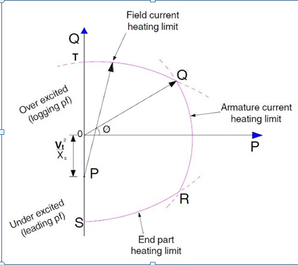
Following points can be observed and noted from the capability curve:
1) Armature heating and field heating limits are shown by curve QR and QT respectively. Both these curve cut at point Q which means the generator shall be operated at this point under lagging load condition.
2) End part heating is shown by curve RS for leading load condition. It shall be noted that armature heating limit and end part heating limit curves cut each other at point R. This point is the point of operation of generator under leading load condition.
3) Generator operation shall always be confined within the capability curve at all the time else it may damage due to overheating.
4) Capability Curve is supplied by the manufacturer and works as a guideline for operator of generator.
5) Capability Curve is all about heating of different parts. This means that if the cooling of machine is increased then the limits of generator operation will also increase. This means the individual limits will increase and the operation boundary will broaden

Good article.