
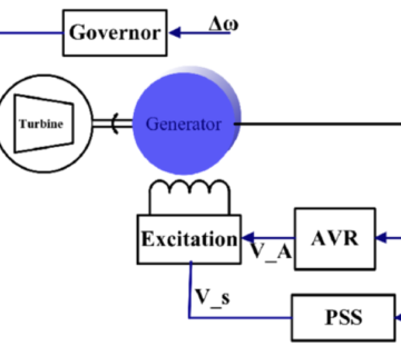
ELECTRICAL CHARACTERISTICS OF TRANSMISSION LINES & BASIC CLASSIFICATION OF LINE LENGTH:
Electrical power is transferred from generating stations to consumers through overhead lines and cables.
Overhead lines are used for long distances in open country and rural areas, whereas cables are used for underground transmission in urban areas and for underwater crossings. For the same rating, cables are 10 to 15 times more expensive than overhead lines and they are therefore only used in special situations where overhead lines cannot be used: the distance in applications are short.
Since all cables are subject to the same impacts despite their differences, an equivalent circuit diagram for one cable may be drawn, as illustrated in Figure 1. The transmission line is affected by an ohmic series resistor R, a line inductance L, an insulation value G, and a line capacitance C.
![]()
(a) Overhead lines
A transmission line is characterized by four parameters: series resistance R due to the conductor resistivity, shunt conductance G due to leakage currents between the phases and ground, series inductance L due to magnetic field surrounding the conductors, and shunt capacitance C due to the electric field between conductors.
Series Resistance (R)
The resistances of lines accounting for stranding and skin effect are determined from manufacturers tables.
With the formula the resistance can be described as:
𝑹 = 𝝆𝒍/𝑨 (1)
R = series resistance in [Ω]
l = length of the conductor in [m]
A = cross-sectional area of the conductor in [mm²]
ρ = specific resistance in [Ω·mm²/m]
Shunt Conductance (G)
The shunt conductance represents losses due to leakage currents along insulator strings and corona. In power lines, its effect is small and usually neglected.
In the practise, there’s not any ideal insulator which is without any electric current. As a result, a leak current flowing across the insulation between the two wires appears at an isolated two-wire line as well. G is the value of the conducting ability, which is also known as cross-resistance or derivation. The S (“Siemens”) is used as a conductance measuring unit.
𝑮 = 𝟏/𝑹 (2)
Series Inductance (L)
A magnetic field builds itself up around any conductor current kept flowing through. The magnetic field varies in proportion to the alternating voltage calculated. Through this, a tension that counteracts her cause is induced in the conductor. The current flow is weakened by the induced voltage. The inductor L’s value is determined by the following factors:
- the conductor’s length;
- the conductor’s cross-sectional area and
- the separation between the wires
Line inductance is determined by partial flux linkages inside the conductor cross section as well as external flux linkages. In the case of overhead lines, the inductances of the three phases differ unless the conductors are spaced equilaterally, which is not commonly used. The inductances of the three phases with non-equilateral spacing can be equalised by transposing the lines so that each Phase occupies all three feasible positions successively. The inductance per phase of a transposed three-phase line is,
![]()
In the above equation, 𝐷𝑠 , is the self-geometric mean distance, taking into account the conductor composition, stranding, and bundling; it is also called the geometric mean radius. And 𝐷𝑒𝑞 is the geometric mean of the distances between the conductors of the three phases a, b, and c:
![]()
Shunt Capacitance (C)
The potential difference between the conductors of a transmission line causes the conductors to be charged; the charge per unit of potential difference is the capacitance between conductors. When alternating voltages are applied to the conductors, a charging current flows due to alternate charging and discharging of the capacitances.
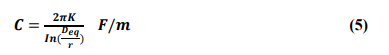
where r is the conductor radius, Deq is given by Equation 4, and k is the permittivity of the dielectric medium. For parallel-circuit lines, the “modified geometric mean distance” of the conductors of the same phase replaces r in Equation 5.
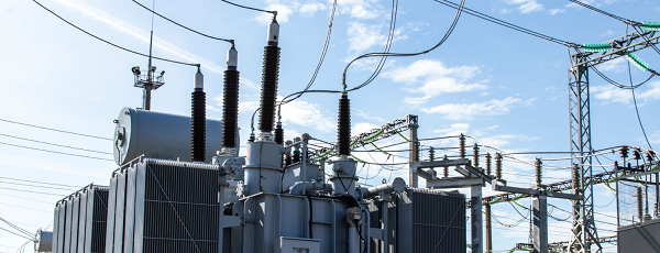
(b) Underground cables
The basic parameters of underground cables are the same as those of overhead lines: series resistance and inductance; shunt capacitance and conductance. For the following reasons, the values of the parameters, and hence the characteristics of cables, differ significantly from those of overhead lines:
1. The conductors in a cable are much closer to each other than are the conductors of overhead lines.
2. The conductors in a cable are surrounded by metallic bodies such as shields, lead or aluminium sheets, and steel pipes.
3. The insulating material between conductors in a cable is usually impregnated paper, low-viscosity oil, or an inert gas.
BASIC CLASSIFICATION OF LINE LENGTH:
Overhead lines may be classified according to length, based on the approximations justified in their modelling:
a) Short lines: lines that are less than 80 kilometres long (50 mi). They have negligible shunt capacitance, and may be represented by their series impedance.
b) Medium-length lines: lines with lengths ranging from 80 to 200 kilometres (125 mi). The nominal equivalent circuit can be used to represent them.
c) Long lines are those that are more than 200 kilometres long. For such lines the distributed effects of the parameters are significant. They need to be represented by the equivalent circuit. Alternatively, they may be represented by cascaded sections of shorter lengths, with each section represented by a nominal equivalent.
Pradeep Periasami
– Power System Engineer

No comment