
Reactive Power Compensation and Extraction from Generator
1. INTRODUCTION
Reactive Power Compensation – Synchronous Generators employed by Independent Power Producers (IPPs) not only participating in Energy market but also participate in Ancillary Service Market. Ancillary Services are support services which are required for improving and enhancing the reliability and security of the electrical power system. The reactive power requirements and voltage control becomes critical aspect of grid management with wide varying loads and large renewables penetration. Therefore, the provision of reactive power is required which could be allowed under reactive power support ancillary services.
Synchronous Generator has the capability to absorb or generate reactive power This article explore the role of OLTC in Generator Transformer (GT) in extracting the reactive power from the generator.
2. OBJECTIVE
Objective of the article is to explore the following
– Role of OLTC in Generator Transformers
– Reactive power capability of Generators
– Extracting the reactive power capability to grid
– Role of OLTC Range and impedance of transformer
3. SYSTEM MODELLING
A 50 MW rated generator having power factor of 0.8 lag and 0.95 lead is connected to the Utility through GT (11/132kV) and a transmission line (Tr Line). The generator terminal voltage is Vg, the High Voltage (HV) side of Generator Transformer (GT) is Vt and Utility voltage is Vs.
❖ 𝑸𝒎𝒂𝒙 is the maximum reactive power a generator can generate and the value of 𝑸𝒎𝒂𝒙 for 50 MW generator is 37.5 Mvar.
❖ 𝑸𝒎𝒊𝒏 is the maximum reactive power a generator can absorb and the value of 𝑸𝒎𝒊𝒏 for 50 MW generator is -16.434 Mvar.
❖ The tap range considered for GT provided with OLTC is + 10% to -10% in steps of 1.25%
4. CASES WITH SIMULATION RESULTS
➢ Cases with grid voltage variation
I. With 100% Grid Voltage
II. With 90% Grid Voltage
III. With 110% Grid Voltage
➢ Cases with reactive power extraction/absorption
IV. Maximum Reactive power Extraction from Generator
V. Maximum Reactive power absorption by Generator
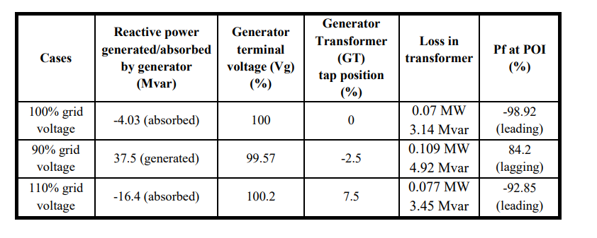
CASE (I) With 100% Grid Voltage

For the given system with 100% grid voltage, real power injected to grid is 49.5 MW and, the reactive power absorbed from grid is 7.35 Mvar
• At PCC leading power factor of 98.92% is observed.
• The generator terminal voltage (Vg) is maintained at 100% and the loss in Generator transformer (GT) at 0% tap having impedance of 12.5% is 0.07 MW and 3.14 Mvar.
• At 100% grid voltage, generator absorbs reactive power of 4.03 Mvar.
CASE (II) With 90% Grid Voltage
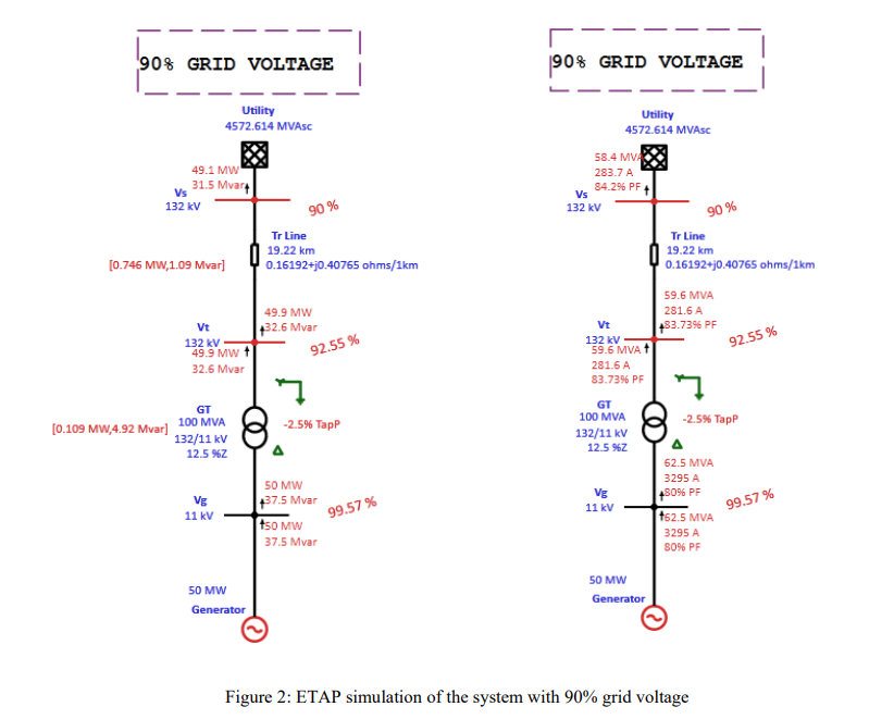
- For the given system with 90% grid voltage, real power injected to grid is 49.1 MW and, the reactive power injected to the grid is 31.5 Mvar.
- At PCC lagging power factor of 84.2% is observed.
- The generator terminal voltage is (Vg) is maintained at 99.57%
- When the grid voltage is at 90%, the tap position of generator transformer (GT) is at -2.5% and the loss of transformer at -2.5% tap is 0.109 MW and 4.92 Mvar which is higher than CASE I.
- At 90% grid voltage, generator supplies reactive power of 37.5 Mvar.
CASE (III) With 110% Grid Voltage
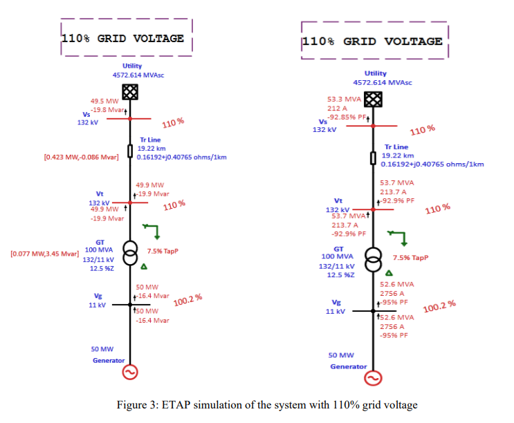
For the given system with 110% grid voltage, real power injected to grid is 49.5 MW and, the reactive power absorbed from the grid is 19.8 Mvar.
- At PCC leading power factor of 92.85% is observed.
- The generator terminal voltage (Vg) is maintained at 100.2%
- When the grid voltage is at 110%, the tap position of generator transformer (GT) is at 7.5% and the loss in transformer is 0.077 MW and 3.45 Mvar which is lesser than CASE II.
- At 110% grid voltage, generator absorbs reactive power of 16.4 Mvar
CASE (IV) Maximum Reactive power Extraction from Generator
As we know,
➔ POSITIVE TAP SETTING ON HV SIDE (Vt), DECRESES THE VOLTAGE ON LV SIDE
(Vg)
➔ NEGATIVE TAP SETTING ON HV SIDE (Vt), INCREASES THE VOLTAGE ON LV
SIDE (Vg)
• Hence, in order to extract maximum reactive power of 30.98 Mvar from 50 MW Generator, the positive tap setting on HV of generator transformer (GT) must be increased and therefore, the Generator terminal voltage (Vg) will be reduced.
• Generator will push maximum reactive power in order to maintain Generator terminal voltage (Vg) at 1 pu.
Positive Tap Setting on HV side of GT
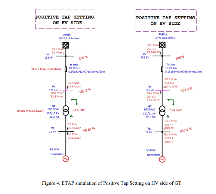
- The tap has been increased to 7.5% on positive side of HV of generator transformer (GT) and so, the Generator terminal voltage (Vg) has been reduced.
- To maintain Generator terminal voltage (Vg) at 1 pu, the generator pushes its maximum reactive power of 37.5 Mvar. Thus, maximum reactive power has been extracted.
- The generator is operating in Voltage Control mode.
- The lagging power factor at Point of Interconnection (POI) observed is 83.84%
Positive Tap Setting on HV side of GT and increasing Generator Terminal Voltage (Vg)
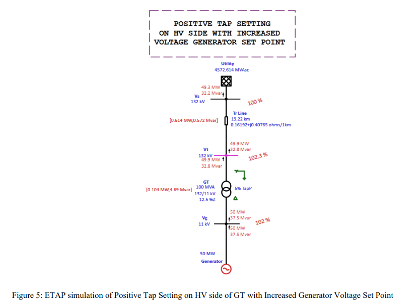
- The maximum reactive power can be extracted from generator by increasing Generator terminal voltage (Vg) set point also with positive tap setting on HV side of generator transformer (GT).
- By increasing the field current, the Generator terminal voltage (Vg) set point can be increased and in the above simulation, the Generator terminal Voltage (Vg) is increased to 1.02 p.u.
- The positive tap setting on HV side of generator transformer (GT) is 5% and hence maximum reactive power of 37.5 Mvar from generator has been extracted.
- The generator is operating in Voltage Control mode.
- The power factor at Point of Interconnection (POI) is 83.69%.
Possible Breach of Power Purchase Agreement (PPA)
- It is possible that the generators (Ancillary Services) may get lured by the high cost of dispatch under Frequency Support Ancillary Services (FSAS). This may result into a situation where some generators try to breach the contracts/PPAs in order to supply power under FSAS.
- It is necessary to ensure that generators (Ancillary Services) do not give preference to FSAS at the cost of their PPAs.
Inferences on CASE(I)
- The usefulness of specifying “INHERENT TAP” for generator transformer (GT) is evident now. The generator voltage mentioned here is 11kV and system voltage is 132 kV, it is desirable to specify the no load voltage ratio (Turns Ratio) of generator transformer (GT) as 11/138 kV.
- In this case, the “INHERENT TAP” is 4.6% (138/132), almost accounting for full load regulation.
- Hence, the Generator terminal voltage (Vg) of generator need not to be raised very high to generate substantial reactive power.
- ETAP simulation is attached below with Inherent Tap setting of generator transformer (GT) voltage rated at 11/138 kV with Generator Terminal Voltage (Vg) of 1 pu.
- Let us consider the power factor to be maintained at POI is 90 % lagging to 95% leading

- From the above simulation results, it is shown that without breaching PPA, generator can supply 22.3 Mvar reactive power which maintains lagging power factor of 93.82% at POI.
- Figure 6, shows the simulation with inherent tapping of generator transformer (GT) and the results can be obtained without breaching PPA.
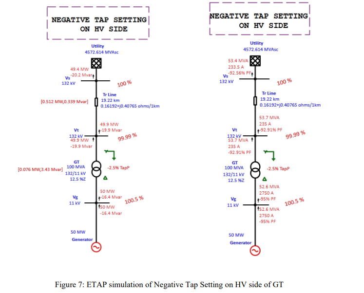
CASE (II) Maximum Reactive power Absorption from Generator
- We know from CASE (IV) that NEGATIVE TAP SETTING ON HV SIDE (Vt), INCREASES THE VOLTAGE ON LV SIDE (Vg).
- In figure 7, due to the Negative Tap setting on HV side of generator transformer (GT), Generator Terminal Voltage (Vg) increases and hence, generator absorbs reactive power maintaining Generator Terminal Voltage (Vg) at 100.5 pu.
- The ETAP simulation attached below shows, having negative tap of -2.5% on HV of OLTC of generator transformer (GT), the generator absorbs reactive power of 16.43 Mvar which is the maximum limit for the generator to absorb.
- The generator is operating in voltage control mode and from figure 6, at POI leading power factor of 92.56% is noted
5. REMARKS
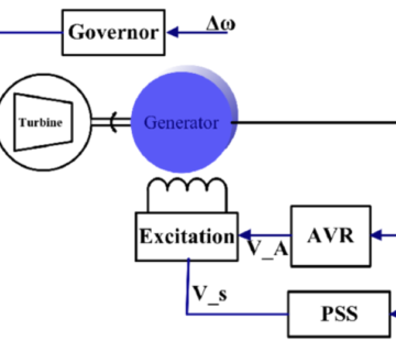
- Most of the excitation systems are provided with OEL (Over Excitation Limiter) and UEL (Under Excitation Limiter). OEL is set to limit the reactive output from the generator to prevent rotor overheating. UEL is set to limit the reactive absorption by the generator so that the stability of the unit is not endangered.
- For high positive or negative tap of OLTC, when generator hit either of the limits, further increase or decrease of reactive power from generator cannot be achieved.
- Extreme caution is needed when reducing taps, which cause increase in voltage at generator terminal leading to tripping of generator on over voltage or on loss of field protection.
- If the generator trips on over-voltage (59) or loss of field protection (40) protection, it is necessary to review the operation of AVR control modes and tap changer before suspecting wrong relay operation.
6. CONCLUSION
- Many GTs in practice are not provided with OLTCs but some are provided with OLTCs and it may appear ‘appealing’ to go for a large tap range (e.g., +10% to -10%) to have better control over plant voltages, but from the above analysis, it can be seen that the operation of OLTC is closely linked with the reactive power capability of the generator.
- Even if the generators are having surplus capacity to generate or absorb reactive power to support Frequency Support Ancillary Services (FSAS), it is to be ensured that generators should not breach PPAs.
7. REFERENCES
- Monograph of I EEMA articles of Dr. K. Rajamani, Chapter 2.
- CERC Staff paper on “Introduction of Ancillary Services in Indian Electricity Market”, April 2013 http://cercind.gov.in/2013/whatsnew/SP13.pdf
- C. Tufon, A. Isemonger, B. Kirby, J. Kueck, and F. F. Li, “A Tariff for Reactive Power,” Oak Ridge National Laboratory, Oak Ridge, TN, ORNL/TM-2008/083, July 2008.


Great ..Thanks….
VERY VERY IMMPESIVE ARTICEL THANK YOU VERY MUCH
Excellent
Thanks for useful article
IT IS SO MUCH USEFUL FOR ELECTRICAL ENGINEERS
Great contribution
Very Informative