METHODS OF REDUCING SHORT CIRCUIT CURRENT
An electrical circuit in which a very low resistance path has been accidently opened. When the resistance in a circuit decreases the current in the circuit increases drastically, which can damage the circuit and cause fires. As a result, we have used certain equipment and other concepts in order to reduce the short circuit current.
Increasing the cable length:
There are numerous approaches available to minimize the fault current in a low voltage system. Increasing the cable length is one technique.
The fault current in bus 03 is 24.997 kA, and the cable length is 30 meters. However, because the breaking current of a low voltage circuit breaker is 20 kA, increasing the cable length from 30 to 50 meters. reduces the fault current to within 20 kA. The fault current on bus 03 is now 19.024kA.The fault current will decrease when the cable length is increased. that is shown the
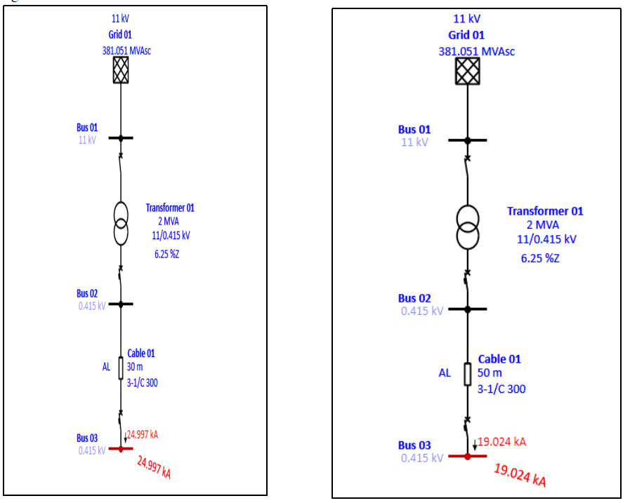
Figure 1: Etap simulation for different cable length
Lighting transformers:
Lighting transformer is nothing but a 1:1 transformer .the transformer turns ratio is the number of turns of the primary winding divided by the number of turns of the secondary coil
The fault current in bus 03 is 24.997 kA, and the cable length is 30 meters. However, because the breaking current of a low voltage circuit breaker is 20 kA, we have installed a lighting transformer between cable and bus 03. The fault current is now within20 kA of the safe limit. The fault current on bus 03 is now 10.707 kA. The fault current will be reduced shown in figure 2.

Figure 2: with unit ratio transformer
There are numerous approaches available to minimize the fault current in a medium voltage system. One option is to use a current limiting reactor.
Current limiting reactor:
limiting fault current. Although the CLR introduces impedance into the circuit degrading the voltage profile during normal operation, it can be a cost-effective solution obviating the need for upgrading switchgear in the system due to increase in the fault level. A current limiting reactor (CLR) is a series reactor connected into the circuit for limiting fault current. Above the result is fault current limit the some values .

Figure 3 : application of IS limiter
Applications of the CLR for limiting fault level are varied. One of the more attractive applications is often the bus section application; see Figure 3 (a). For this arrangement, the CLR is placed between two bus bars to connect them together. This arrangement will be analysed in more detail later in this report.
Disadvantages
- Voltage drop
- Increasing power loss
- Reduce the grid power factor
- High space require
The system bus 03fault current is 19.318 kA in normal conditions. However, as the system power is increased to 15 MW for internal purposes by employing one generator, the fault current has increased to 24.672 kA, as shown in figure. How to reduce the fault current? Whenever we have use some methods, that’s are given below.
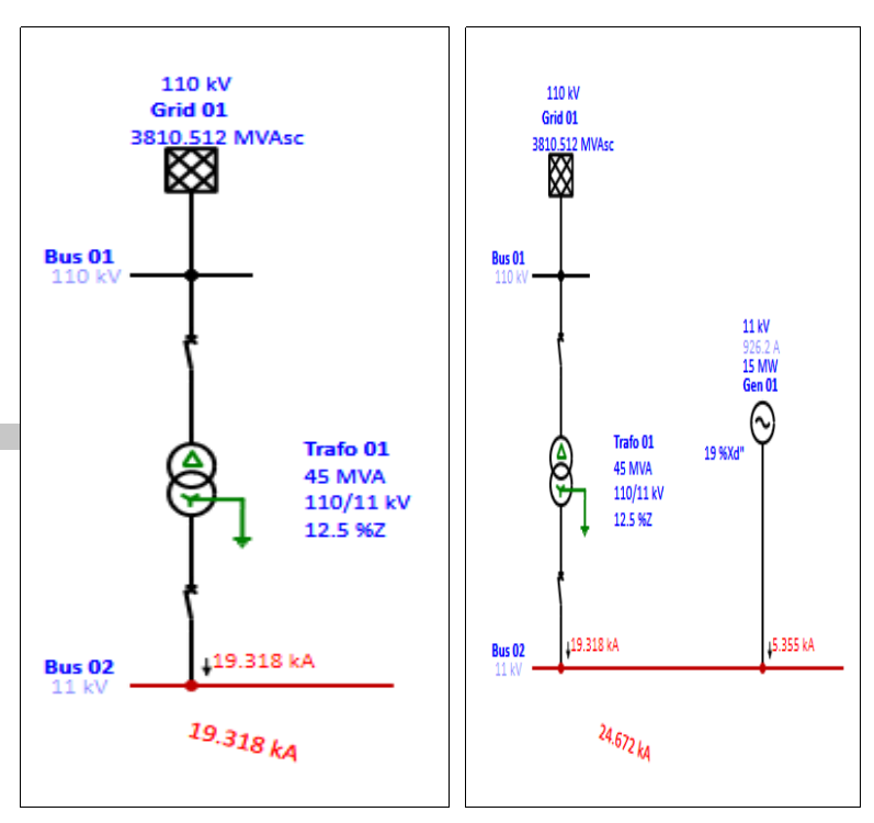
Figure 4: add a generator
Current limiting reactor:
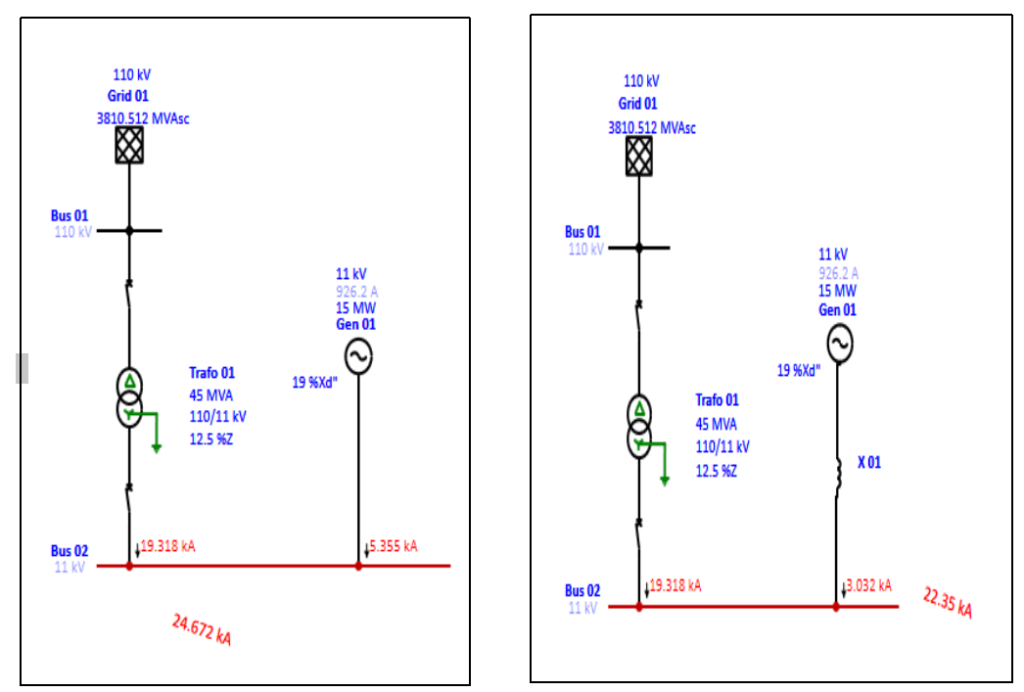
Figure 5: With current limiting reactor
The fault current will be reduced from bus 02 is 24.672 kA to 22.35 kA as a result of the above results. The fault current will be reduced if the reactor impedance is increased.
Unit ratio transformer:
The number of turns on a transformer’s secondary divided by the number of turns on its primary is known as the turns ratio. If the unit ratio transformer is connected between generator bus 02, Previously, the fault current of bus 02 was 24.672 kA. The fault current is now reduced from 24.672 kA to 19.874 kA. The Etap result is depicted in the diagram below.
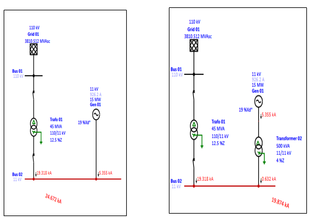
Figure 6: with unit ratio transformer
IS limiter
Is limiter is product of ABB
It is a world fastest switching device
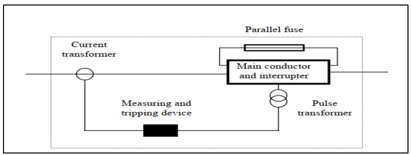
Figure 7: Circuit diagram of IS limiter
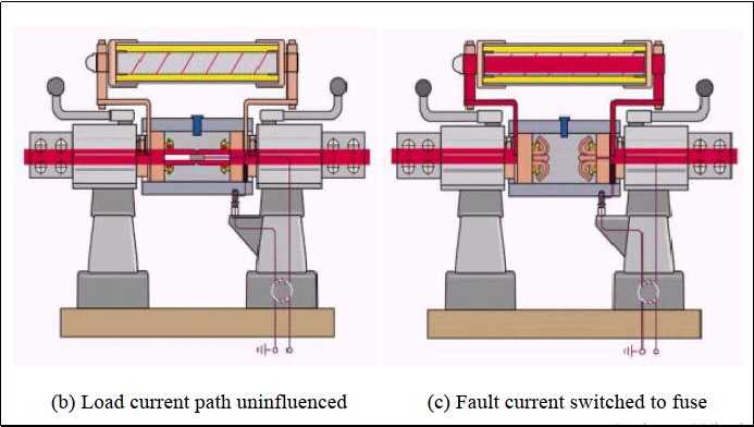
Figure 8:with fault current and with out fault current
The Is-limiter consists of two parallel conductors: a main conductor and a parallel fuse. Under normal operation, the load current flows through the main conductor.
During a fault, a tripping device disconnects the main conductor, transferring the fault current to the parallel fuse with a high breaking capacity, which limits the fault current during the first rise (in less than 1 ms) . The main applications of the Is-limiter are shown in Figure 9 .
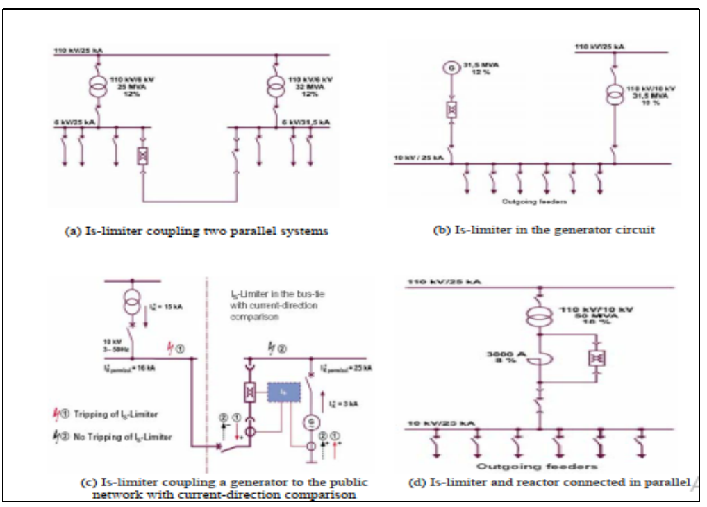
Figure 9: Various application of IS limiter
The Is-limiter is often used to couple two systems or parts of systems (as shown in
Figure 9(a), whose short-circuit withstand capability would not be sufficient if connected in parallel via a circuit breaker. The Is-limiter separates the system electrically into two parts before the fault current can endanger the system components.
Figure 9(b) shows the Is-limiter protecting a public supply system from the short circuit current supplied by the DG.
Figure 9(c) shows the Is-limiter installed in the connection between the public supply and the DG. The Is-limiter can interrupt the fault current supplied by the DG with a current-direction comparison.
Figure 9(d) shows the Is-limiter connected with a reactor in parallel. This arrangement can avoid the copper losses, large voltage fluctuations and the electromagnetic fields caused by the reactor.
Network splitting:
In practice, a much more common and less expensive approach to fault level reduction is network splitting
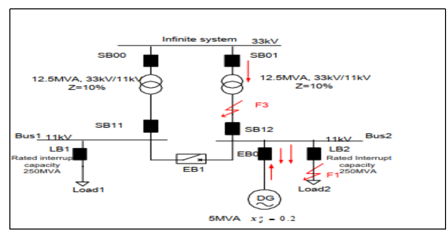
Figure 12:without individual circuit breaker in DG
The bus-section circuit breaker EB1 is located between Bus1 and Bus2 in the network splitting design described in Figure. The impedance between the 33kV and 11kV systems increases from 5% to 10% as a result of this network split, greatly reducing the fault current from the public supply (33kV).
However, this system may limit the DG’s freedom. Because the DG must be isolated from the network when busbar Bus2 for maintenance, an alternative network splitting design that overcomes this difficulty is presented in Figure 12.
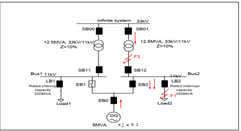
Figure 13:with individual circuit breaker of DG
Figure 13 shows that an additional EB2 circuit breaker is required, but the network’s flexibility and safety, as well as the DGs’, are enhanced. Normally, the circuit breaker EB1 is open, dividing the 11kV busbar into two sections, Bus1 and Bus2. LB2 can safely interrupt fault current for fault F1 within its rated capacity. By closing EB1, the DG and Load2 can be relocated to Bus1 after a fault F3 has been cleared. When busbar Bus2 requires maintenance, the DG can be moved to Bus1 by closing EB1.
Reference:
- UN, Earth Summit, United Nations Conference on Environment and Development (UNCED), Rio de Janeiro, June 3-14, 1992. http://www.un.org/geninfo/bp/enviro.html
- UNFCC, Text of the Kyoto Protocol, http://unfccc.int
- ETSU/DTI, New and Renewable Energy: Prospects in the UK for the 21st Century: Supporting Analysis, March 1999.
- ABB, Is-limiter, ABB Calor Emag, 2002, http://www.abb.de/calorUNFCC, Text of the Kyoto Protocol, http://unfccc.int
- Engineering Technical Report No.113, Notes for guidance for the protection of private generating sets up to 5MW for operation in parallel with electricity suppliers’ distribution system, 1995.


very very useful sir . thanks very much
Good explanation of basics and methos with can be practically possible to apply.