
LV RELEASE SETTING (low voltage):
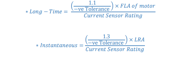
LV setting for downstream, such as end equipment like motor and capacitor banks, the release has to trip instantaneously at minimum time delay. But for the lumped loads relay or release and cables are not required. The following equation used to evaluate the release setting in distribution system.
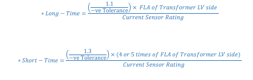
Release setting for Transformer LV side, there is no need of instantaneous tripping, but the tripping characteristic curve should not intersect with tripping characteristic curve of other equipment’s. There are two methods to evaluate the release setting of Transformer LV side. Method 1: If the number of loads or motors are known and there is no future addition of loads

Method 2: If the loads are not known and in case addition of future loads,
While considering Bus coupler, the highest loaded Bus is taken and the release setting is given for the LV Circuit Breaker and Co-ordination is performed.
For Ground,
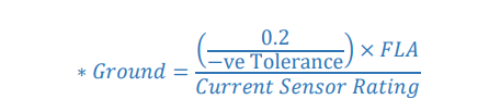
• FLA – Full Load Ampere
• LRA – Locked Rotor Ampere
• -ve Tolerance – Negative Tolerance
HV/MV RELAY SETTING (high/medium voltage):
The current transformer is used to sense the current in the network. It feeds the current to the relay. If the current exceeds the set value in relay, it gives trip command to the breaker.
Inverse Definite Minimum Time:

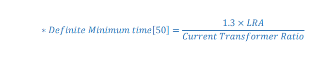
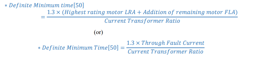
Definite Minimum Time:
50 Protection for motor:
50 Protection for Transformer:
There are two methods adopted for transformer protection. The setting can be calculated either by
considering connected load as reference or by considering transformer rating.
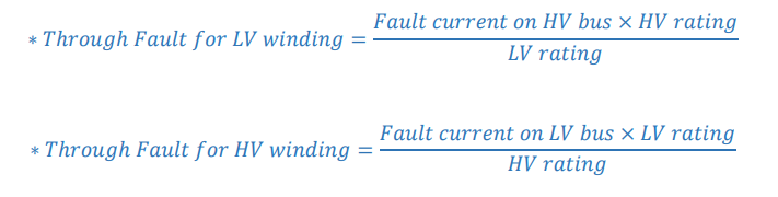
How to find Through Fault Current:
For Earth Fault Protection

In case of RMU, the fault is consider both in LV and HV side. For the RMU the equation for relay setting is mentioned below,

Addition of FLA means e.g.: if there are three transformer, the FLA of three transformer has to be added and then the relay overcurrent setting has been given

Highest Through Fault current means e.g.: if there are three transformer, the highest rating transformer’s through fault current is taken and remaining FLA of
other two transformer is added with highest through fault current and instantaneous setting has been given.
NOTE:
• For LV co-ordination the clear space between the tripping characteristic curves should be maintained for perfect co-ordination.
• For HV/MV co-ordination Time and Current discrimination should be considered for perfect co-ordination. (Time discrimination for one and other
relay is 200ms).
COORDINATION TIME INTERVAL: (IEEE 242)


No comment