
Grounding study report
Purpose
The purpose of this document to outline the basic considerations for grounding design for any type of plant or substation. This document describes design criteria, design procedures, software methods etc. Based on project nature, some of the calculations may not be required or to be included, Reader should understand technically what is relevant to project and start preparing the report
Scope
The main objective or scope of this report to find out Main Grounding conductors based on ground fault current.
To calculate resistance of Grounding system and verify less than 1 ohm and the Ground Potential Rise (GPR).
To estimate the touch and step voltages during faults and to verify that actual touch and step voltages are within the limits as per IEEE-80 safety threshold limits
This report does not GIS substation Grounding requirements
Reference documents and standards
- Owner specification
- Electrical design basis
- Grounding materials specification
- IEEE 80-2013
Abbreviations / Definitions
In this section All the abbreviations used in the report to be included and definitions to be used
Power System description
In the section brief description of electrical network for the project to be explained for the reader to understand quickly. It briefly explains about system grounding method adopted for the project for each voltage level
Assumptions
If any assumptions considered in the absence of input data to be added in this section
Input Data and Design Considerations
In this section the below information to be included typically
- Environmental conditions
- Soil resistivity (uniform / two layer / multi-layer)
- Single to ground fault current at each voltage level
- Fault clearing time at each voltage level
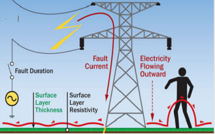
- Surface layer thickness and resistivity
- Selection of conductors (Horizontal and vertical) and its joints
- Facility Plot plan
- Length of conductor (this can be obtained from the preliminary grounding plan prepared)
- Grounding for protection against accidental contacts
- Grounding for protection against static electricity
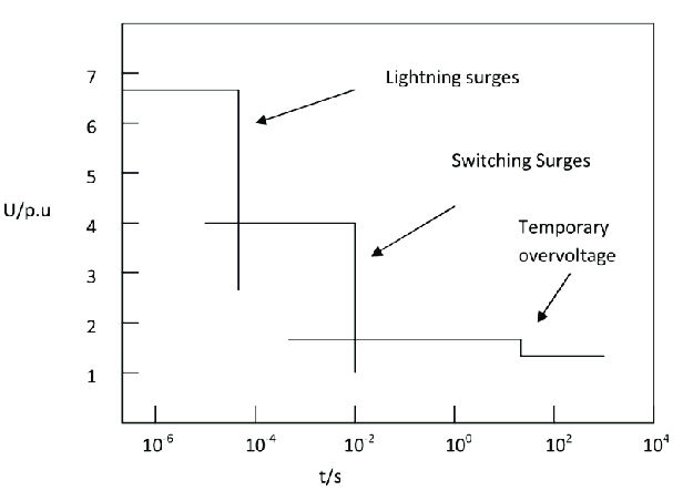
- Grounding for protection against Lightning
Basic safety considerations
Tolerable body current limit,
As per IEEE 80, Shock current that can be survived by 99.5% of persons (weighing approximately 50kg which is worst, when we consider for 50kg, the same design applicable for persons weighing 70kg.

Where:
IB = rms magnitude of tolerable shock current through the body in Amperes.
ts = Duration of the current exposure in sec (Shock duration).
Design Procedure:
Step 1: Field data.
Total area enclosed by ground grid (A) & Soil Resistivity (P) are required.
Soil Resistivity test is to be carried out with Wenner’s Bridge. Soils Resistivity profile & model (i.e. Uniform or two layer model or Multi-Layer) are required. Soil can be considered uniform if the difference between two extreme resistivity values of the field test data is 30% or less.
In this case simply average of all the resistivity values is to be used. Or
We can use software’s to analysis soil model as well.
Step 2: Conductor Size
The minimum conductor size (in mm²) is calculated based on following formula:

where:
If = Symmetrical ground fault current in “kA”.
A = Conductor cross section in “mm²”
Tm = Fusing temperature in (maximum allowable temperature) in “°C”
Ta = Ambient temperature in “°C”
αr = Thermal coefficient of resistivity of conductor material at reference temperature Tr in “1 / ºC”
ρr = Resistivity of the ground conductor at referenced temperature Tr in “micro-ohms cm”
tc = Maximum possible clearing time.
Step 3: Touch and step criteria.
Permissible step and touch voltages are given by the following formulae for a body
weight of 50kg:

Where,
1000 = Resistance of a human body in ohms from hand-to-both feet, from
hand-to-hand, and from one foot to the other foot.
Cs = Reduction factor
hs = Thickness of the soil protective surface layer in meter
ts = Duration of the shock current is in seconds.
ρs = Resistivity of the surfacing material in ohms-meter which ranges from 1000 to 10000 in value.
ρ = Soil resistivity (resistivity of earth beneath the surface material) in ohms-meter.
Initial Design: Step-4 (D,n,L,h)
The preliminary design should include a conductor loop surrounding the entire grounded area plus adequate cross conductors to provide convenient access for equipment grounds. The initial estimates of conductor spacing and ground rod locations. It should be based on (IG) the Maximum grid current that flows between ground grid and surrounding earth (including D.C. offset) in amperes. Further following factors shall be decided
D = Spacing between parallel conductors in meters.
n = Number of parallel conductors in one direction
L = Total length of grounding system conductor including
Grid & ground rods in meter.
h = Depth of ground grid conductors in meter
Step 5: Determination of grid resistance.
Estimates of the preliminary resistance of the grounding system in uniform soil can be
determined by the equations given in Clause of 14.2 & 14.3 of IEEE-80 2013. For the final design, more accurate estimates of the resistance may be desired.
Software analysis based on modeling the components of the grounding system in detail can compute the resistance with a high degree of accuracy, assuming the
soil model is chosen correctly.
Step 6: Maximum grid current IG.
It can be calculated from following equation:


![]()
Where,
IG = Max. Grid Current in Amperes.
Df = Decrement factor for the entire duration of fault
(tf) found for tf given in second
Cp = Corrective projection factor accounting for the
Relative increase of fault current during the station
Lifespan for a zero future system growth Cp = 1
Ig = r.m.s. symmetrical grid current in Amperes.
Sf = Fault current division factor (split factor)
tf = Duration of fault current in seconds.
Step 7: GPR.
GPR = IG × Rg
Next step is to check whether IG x Rg < Etouch and if it is so Grid Potential Rise (GPR) is below the tolerable touch voltage no further analysis is necessary. Only additional conductor required to provide access to equipment grounds if necessary.
Step 8: Mesh voltage
If Ig x Rg is more than Etouch then, Next condition is Em < Etouch
Step 9: Tolerable Step (Es) and Touch Volage(Em) Criteria


where,
Em = Mesh voltage at the centre of the corner mesh –
for simplified method in volts
ρ = Average soil resistivity
Km = Spacing factor for mesh voltage
Ki = Correction factor for grid geometry
IG = Max. rms current flowing between ground grid &
earth.
Lm = Effective length of Lc + LR for mesh voltage, m
Ls = Effective length of Lc + LR for step voltage, m
Some of formulas are skipped in this section, refer IEEE-80 for more information.
Step 10:
After satisfying the step & touch voltage requirements additional grid conductors & ground rods may be required at the base of surge arresters, transformer Neutrals, Circuit Breakers etc.
Step 11:
If either the step or touch tolerable limits are exceeded, revision of the grid design is
required. These revisions may include smaller conductor spacings, additional ground rods, etc.
Step 12:
After satisfying the step and touch voltage requirements, additional grid and ground rods may be required. The additional grid conductors may be required if the grid design does not include conductors near equipment to be grounded. Additional ground rods may be required at the base of surge arresters, transformer neutrals, etc. The final design should also be reviewed to eliminate hazards due to transferred potential and hazards associated with special areas of concern.
Software analysis and safety evaluation
In this section, brief description about software modelling to be explained. Safety analysis to carried out and scenarios to be considered to be explained in detail.
Software version and module is used to be explained.
Soil Model
Soil Model analysis to be added in this section and basis for the same.
Fault Current injection into grounding grid
In this section covers how fault current injection is done at locations where needed and analyse the same, Spilt factor
Touch and Step Voltage Safety threshold limit calculations
In this section using the software, safety analysis to be carried out and results tabulated
Observations from software results
Final results obtained from software to be shall be tabulated against Tolerable Vs Permissible
Recommendation and conclusions
This section shall summarize the key points
- Main conductor size
- Overall grid resistance
- Step and Touch voltage within the limits
- Any other key observations if needed based on project nature.
Jeyakumar Velusamy
– Power System Engineer


No comment