
CONTINGENCY ANALYSIS
Contingency analysis is most important part of Power system study to assess the capability of the power system to meet the load without violating voltage and equipment loading limits.
It is impractical to design a power system which is free from failures. Faults in the system have to be isolated quickly so that the rest of the system functions without disturbance. Power flow in branches and voltage at all buses in the post fault is completely different from Pre fault conditions. Hence it is recommended to study the steady state behavior of the system after faults &equipment outage. Different equipment outage results in different power flow and voltage. It is difficult if not impossible to find out which outage is critical prior to perform simulation for the same. Hence it is recommended perform simulation to study the steady state behavior system after the outage of various equipments one at a time. This is called contingency analysis.
Contingency analysis is used to study the behavior of a power system, when associated equipment gets outage. A number of operating procedures can be analyzed in contingency conditions, such as the loss of a generator, a transmission line, a transformer, or a load.
Preventing any unscheduled outage in the power system is impossible, and hence analyzing possible outages to predict their consequences is essential. Contingency analysis is an important tool in evaluating power system security. It models any single or multiple outages to predict power system state variables after the disturbance.
The N-1 contingency is a common standard for assessing the security of power systems. According to this criterion, planned power system should withstand against any single component failure without any violation in other component constraints, while supporting all loads in the system.
The N-1 contingency may not be sufficient when multiple component failures take place simultaneously. The N-K contingency analysis is for multiple component failures. The N-K contingency means a power system should be able to withstand K number (2, 3) of component failures simultaneously.
Switching modes of Operation
Power system must have system reliability and continuous operation requirements. Even during outage of any equipment rest of the equipments ensures reliable power supply without violating equipment loading and voltage. The load flow study must include scenarios which show that the system can properly function under special circumstances like the loss or maintenance of transformer and motor, Grid supply failure etc.
Load Flow Scenarios
When load-flow studies are conducted for industrial applications, there are usually a relatively small, finite number of practical scenarios to consider. Any equipment maintenance or failure needs to be considered and analyzed.
Load flow scenario example
Scenario |
Grid Supply |
Transformer 1 |
Transformer 2 |
LV Bus Coupler |
DG |
Normal |
Available |
ON |
ON |
OPEN |
OFF |
N-1 (Transformer Outage) |
Available |
OFF |
ON |
CLOSED |
OFF |
N-1 (Grid Outage) |
Not Available |
OFF |
OFF |
CLOSED |
ON |
Switching modes and Load flow scenarios may vary for different systems according to their respective design. The above typical load flow configuration based on the below system.
System Representation
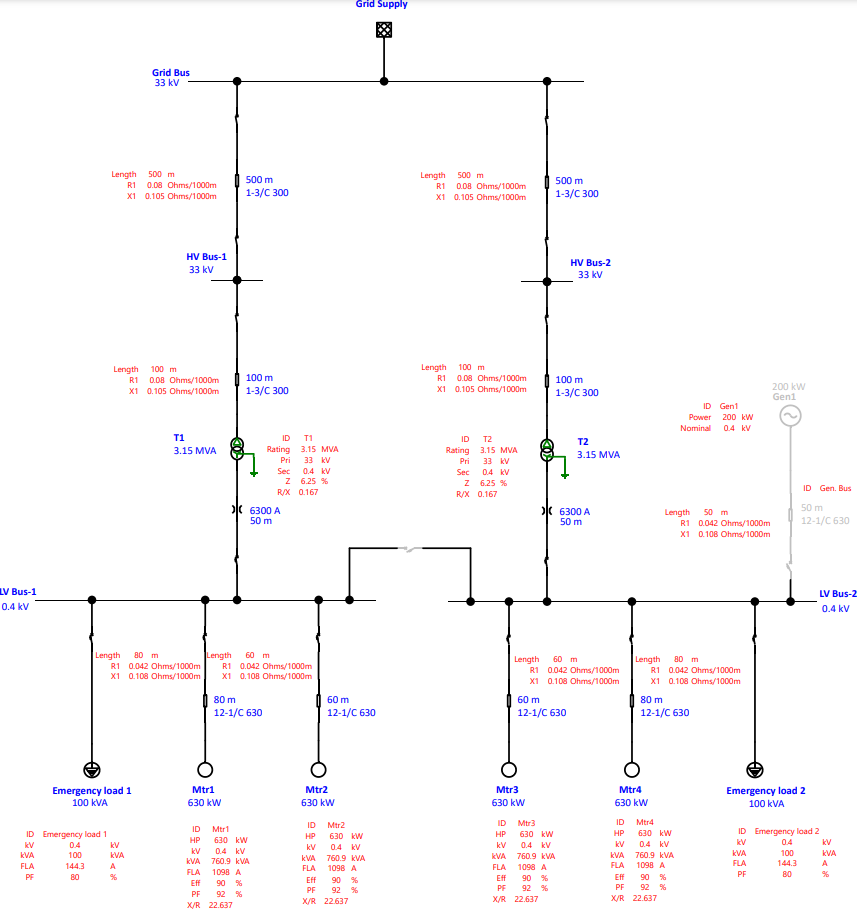
System Description
- The system consists of two voltage levels 33kV and 0.4kV.
- The system receives supply two incomers from single 33 kV Grid.
- The system has HV Bus-1, HV Bus-2and LV Bus-1& LV Bus-2 with bus coupler.
- The system has 2 no’s – 33/0.4 kV, 3.15 MVA transformers T1 & T2.
- The system has 1 no’s – 0.4 kV, 250 kVA diesel generators with generator bus connected to LV Bus-2.
- The system has 4no’s– 630 kW induction motors.
Assumptions
- The transformer %Z and X/R values are considered in accordance with IEC 60076-5.
- Diesel generator modeled in accordance with data sheet.
- Motors are modeled in accordance with data sheet.
- Cables are modeled in accordance with ETAP Library.
- Emergency load 200 kVA shared as 100 kVA each in LV Bus-1 and LV Bus-2.
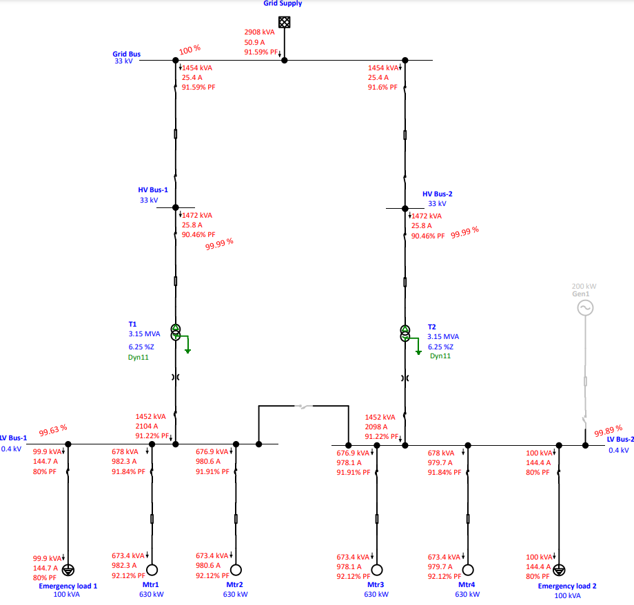
Normal Scenario representation
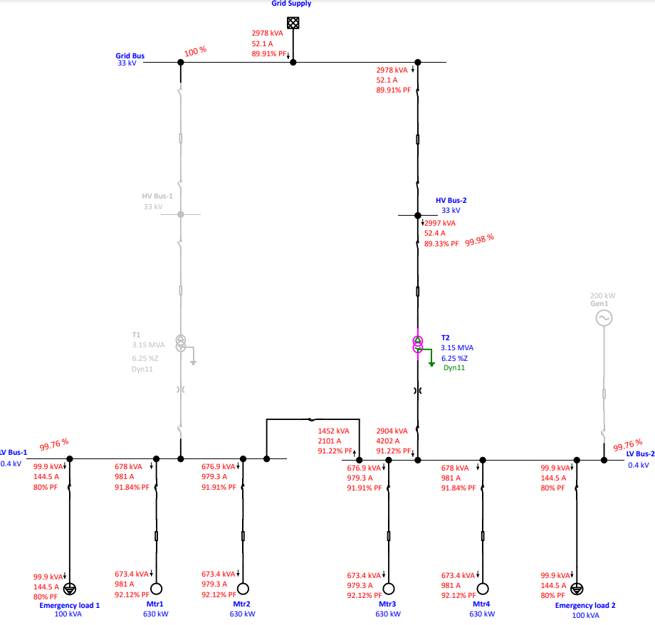
Transformer T1 Outage (N-1) Scenario Representation
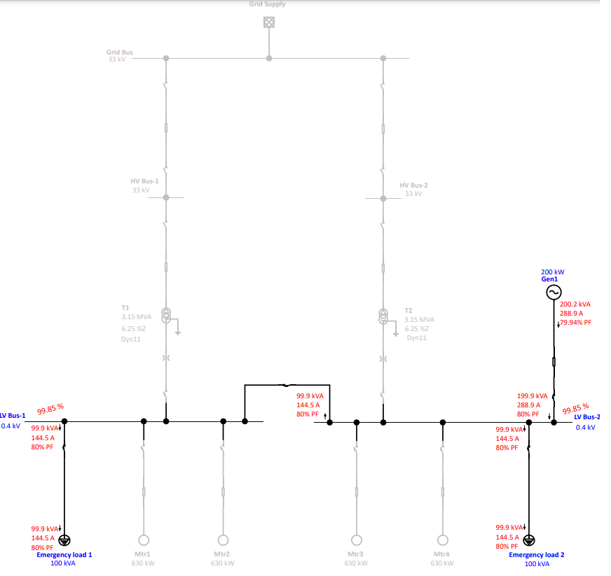
Grid Outage (N-1) Scenario Representation
Contingency analysis results
Source results
|
Source
|
Rated kV
|
Normal | T1 Outage | Emergency |
| MW Generation | MW Generation | MW Generation | ||
| Grid | 33 | 2.673 | 2.693 | – |
| Generator | 0.4 | – | – | 0.17 |
Bus results
|
Bus
|
Nominal kV
|
Normal | T1 Outage | Emergency |
| Voltage % | Voltage % | Voltage % | ||
| Grid Bus | 33 | 100 | 100 | – |
| HV Bus-1 | 33 | 100 | – | – |
| HV Bus-2 | 33 | 100 | 100 | – |
| LV Bus-1 | 0.4 | 99.65 | 99.66 | 99.86 |
| LV Bus-2 | 0.4 | 100.51 | 99.66 | 99.86 |
| Generator Bus | 0.4 | 100 | 100 | 100 |
Transformer loading results
|
Transformer
|
Normal | T1 Outage | Emergency |
| MW Flow | MW Flow | MW Flow | |
| T1 | 1.335 | – | – |
| T2 | 1.337 | 2.692 | – |
Observations from the results
- During normal scenario condition, the system operating all loads with LV bus coupler opened condition.
- During T1 outage scenario, the system operating only with Transformer T2 and all the loads are operating with LV bus coupler closed condition.
- During Grid outage condition, Diesel generator operates the emergency loads in both the busses with LV bus coupler closed condition.
References:
- IEEE Standard 3002.2-2018 – IEEE Recommended Practice for Conducting Load-Flow Studies and Analysis of Industrial and Commercial Power Systems.
- Power Projects load flow course – https://www.powerprojectstraining.com/courses/loadflow

good anna
Excellent
I learned a lot, thank you.
I had a great knowledge of Power System in Power Project. Thanks for guiding me. I got good knowledge. I appreciate it.